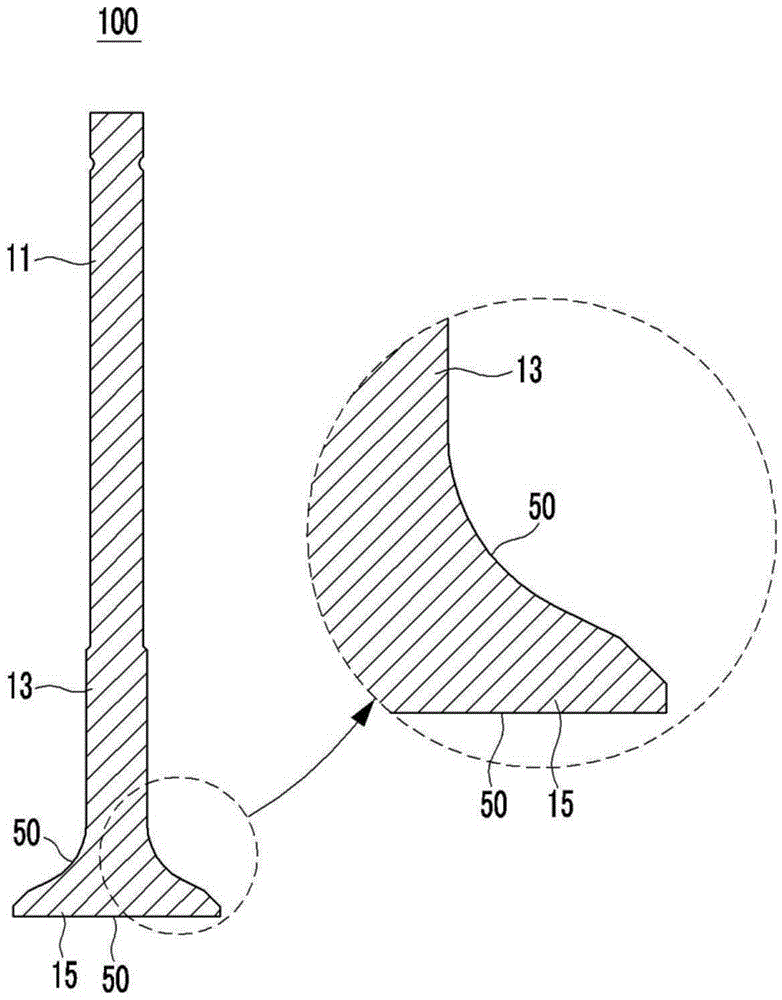
Intake valve for engine
An engine and intake valve technology, applied in the direction of engine components, machines/engines, lift valves, etc., can solve the problems of insufficient progress in the thermal insulation structure of thermal insulation materials, and achieve high mechanical properties, high heat resistance, and improved efficiency. Effect
- Summary
- Abstract
- Description
- Claims
- Application Information
AI Technical Summary
Problems solved by technology
Method used
Image
Examples
Embodiment 1 to 3
[0094] (1) Production of heat insulating coating composition
[0095] Porous silica airgel (specific surface area: about 500cm2) dispersed in ethanol 3 / g) and polyamideimide resin (product manufactured by Solvay SA, weight average molecular weight: about 11,000) dispersed in xylene were injected into a 20 g reactor, zirconia beads (440 g) were added thereto, and heated at room temperature Ball milling is performed at a speed of 150 to 300 rpm under conditions of temperature and normal pressure to produce a thermal insulation coating composition (coating solution).
[0096] In this case, the weight ratio of the porous silica airgel based on the polyamideimide resin is as described in Table 1 below.
[0097] (2) Formation of thermal insulation coating layer
[0098] The resulting thermal insulation coating composition was applied to parts for vehicle engines by spraying. In addition, the thermal insulation coating composition is applied to the part, and the primary semi-dryi...
experiment Embodiment 1
[0109] 1. Experimental Example 1: Measurement of Thermal Conductivity
[0110] The thermal conductivity of the coating layers on the parts from the examples and comparative examples was measured by thermal diffusion measurement based on ASTM E1461 at room temperature and pressure conditions using the laser flash method.
experiment Embodiment 2
[0111] 2. Experimental Example 2: Measurement of heat capacity
[0112] The heat capacity determined by measuring the specific heat of the coating layer on the parts obtained from Examples and Comparative Examples under room temperature conditions using a DSC apparatus based on ASTM E1269 and using sapphire as a control.
[0113] (Table 1)
[0114]
[0115] As described in Table 1, it was confirmed that the heat-insulating coating layers obtained in Examples 1 to 3 had 1240 KJ / m in a thickness of 120 to 200 μm 3 Heat capacity of K or less and thermal conductivity of 0.54 W / m or less. Accordingly, the heat-insulating coating layers obtained in Examples 1 to 3 can be applied to coatings of components of an internal combustion engine to reduce heat energy released to the outside and thereby improve the efficiency of the internal combustion engine and the fuel efficiency of vehicles.
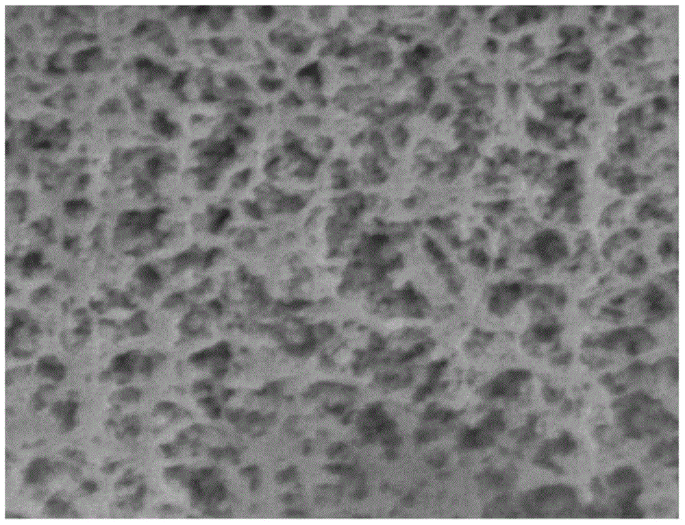
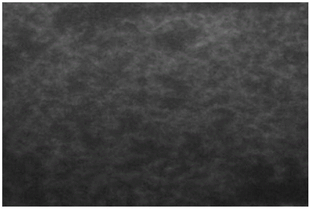
[0116] Additionally, if figure 2 As shown in , it could be confirmed that in the heat ins...
PUM
| Property | Measurement | Unit |
|---|---|---|
| thickness | aaaaa | aaaaa |
| thickness | aaaaa | aaaaa |
| porosity | aaaaa | aaaaa |
Abstract
Description
Claims
Application Information
 - R&D
- Intellectual Property
- Life Sciences
- Materials
- Tech Scout
- Unparalleled Data Quality
- Higher Quality Content
- 60% Fewer Hallucinations
Browse by: Latest US Patents, China's latest patents, Technical Efficacy Thesaurus, Application Domain, Technology Topic, Popular Technical Reports.
© 2025 PatSnap. All rights reserved.Legal|Privacy policy|Modern Slavery Act Transparency Statement|Sitemap|About US| Contact US: help@patsnap.com


