Test device for dynamically measuring fretting pair frictional coefficient during fretting fatigue process and test method

A friction coefficient and fretting fatigue technology, applied in measuring devices, mechanical devices, instruments, etc., can solve the problems of inability to provide fretting fatigue conditions, small driving force of thread loading scheme, and variation of loading normal force, etc. Accurate prediction of fretting fatigue life, reliable test results, and the effect of preventing local stress concentration

Active Publication Date: 2015-11-11
NANJING UNIV OF AERONAUTICS & ASTRONAUTICS
View PDF7 Cites 39 Cited by
  • Summary
  • Abstract
  • Description
  • Claims
  • Application Information

AI Technical Summary

Problems solved by technology

[0004] (1) Fretting fatigue is a multi-axis fatigue problem. Commonly used friction coefficient measurement tools such as: ball-on-disk friction pair and reciprocating friction pair cannot provide fretting fatigue conditions, and can only measure the friction coefficient between conventional contact pairs
[0005] (2) In order to obtain the magnitude and change of the friction coefficient of the fretting pair during the fretting fatigue process, it is necessary to monitor it throughout the process, which requires the measurement of the friction coefficient and the fretting f

Method used


Image

  • Test device for dynamically measuring fretting pair frictional coefficient during fretting fatigue process and test method
  • Test device for dynamically measuring fretting pair frictional coefficient during fretting fatigue process and test method
  • Test device for dynamically measuring fretting pair frictional coefficient during fretting fatigue process and test method

Examples


Embodiment Construction

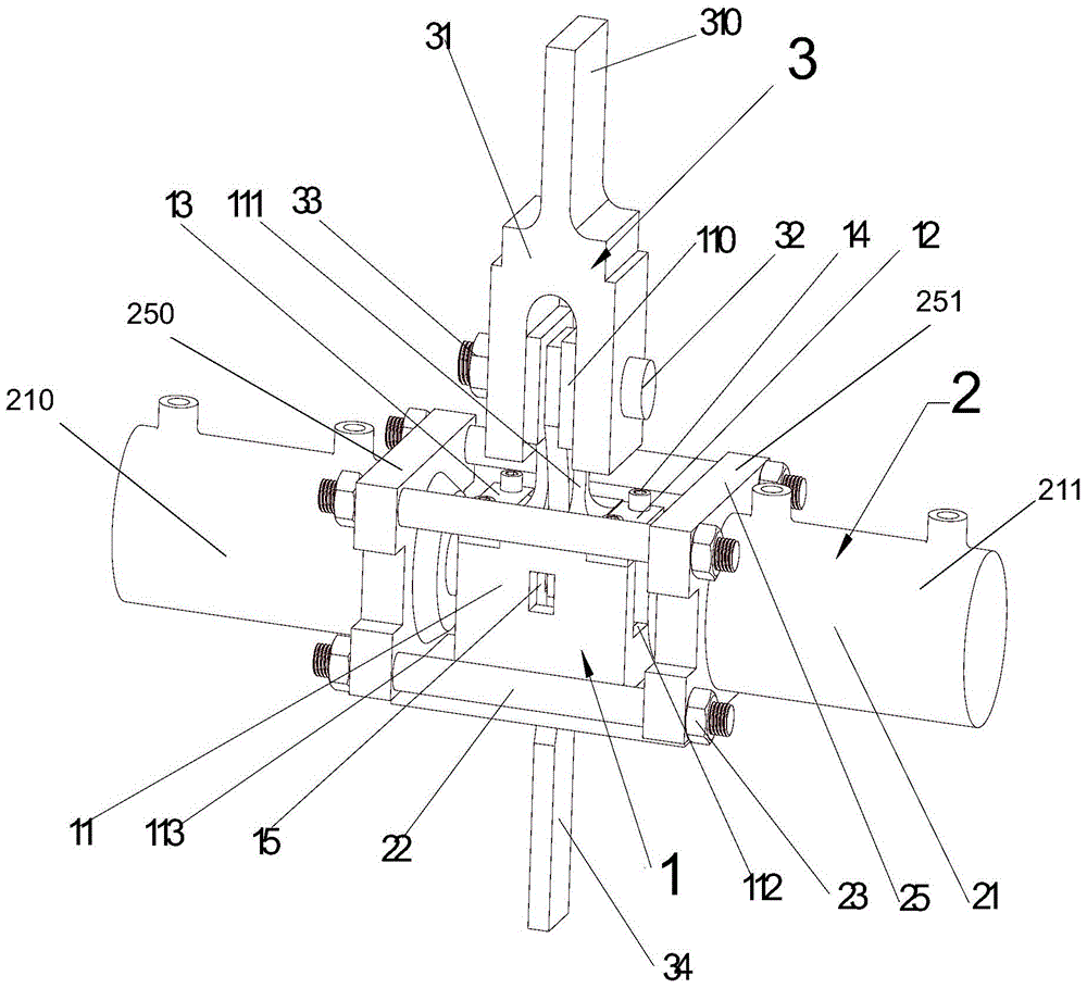
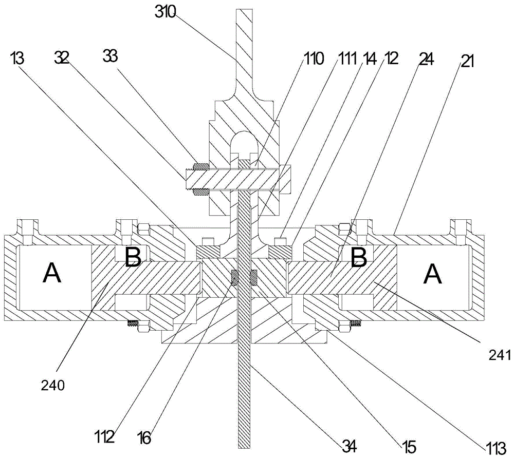
[0046] Please refer to Figure 1 to Figure 8 As shown, the test device for dynamically measuring the friction coefficient of the fretting pair in the process of fretting fatigue according to the present invention includes a friction coefficient measuring component 1 , a normal force loading component 2 and an upper end fixing component 3 .

[0047] The friction coefficient measurement assembly 1 includes a clamp body 11, a first compression cover plate 12 and a second compression cover plate 13 installed on the clamp body 11, an M6 compression bolt 14, a micro-movement pad clamping slider 15 and a micro-movement Pad 16. Wherein the clamping body 11 includes a first suspension part 110 and a second suspension part 117 located at its upper end and spaced apart left and right, extending downward from the lower end of the first suspension part 110 and the lower end of the second suspension part 117 respectively The formed first working part 111 and the second working part 118, th...


PUM


Abstract

The invention provides a test device for dynamically measuring fretting pair frictional coefficient during the fretting fatigue process. A frictional coefficient measurement component realizes the fretting working condition and dynamically measures the frictional coefficient of a fretting pair formed by the cooperation of a fretting section and a fretting pad of a test piece during the fretting fatigue process; a normal force loading component realizes load applying in the horizontal direction; an upper-end fixing component realizes the fixing of the test piece and a clamp body; the horizontal direction loading in the fretting fatigue test is realized by adopting a hydraulic system; the loading system adopts a closed force system frame structure; the piston rods of hydraulic cylinders pushes the fretting pad to clamp a sliding block to move in a sliding groove in the clamp body; the frictional coefficient measurement component is fixed on the upper-end fixing component through a pin bolt; in the vertical direction, except the own gravity and the gravity of the hydraulic cylinder, the frictional coefficient measurement component only receives the frictional force produced due to fretting action between the test piece and the fretting pad; by adhering a strain piece to the working section of the clamp body and calibrating, dynamic monitoring of the frictional coefficient of the fretting pair during the fretting fatigue test process is realized.

Description

Technical field: [0001] The invention relates to a test device and a test method for dynamically measuring the friction coefficient of a fretting pair in a fretting fatigue process, belonging to the technical field of life evaluation tests of materials and structural parts. Background technique: [0002] The aero-engine is the heart of the aircraft, with a complex structure, and a considerable part of the parts have fretting fatigue, some of which are key parts, such as the connection between the compressor and turbine disk and blade, the connection between the disk and the shaft, etc. For some high Due to the influence of fretting fatigue, the service life of components with long service life will decrease by more than 30%. If this phenomenon is underestimated, it may become the root cause of accidents. Fretting fatigue is a contact problem. The main factors affecting fretting fatigue life are: slip amplitude, contact pressure, load frequency, gas environment and humidity, ...

Claims


Application Information

Patent Timeline
IPC IPC(8): G01N19/02
Inventor 董磊崔海涛李爱民
Owner NANJING UNIV OF AERONAUTICS & ASTRONAUTICS
Why Eureka
Try Eureka