

Stress test system based on digital image correlation method and application thereof
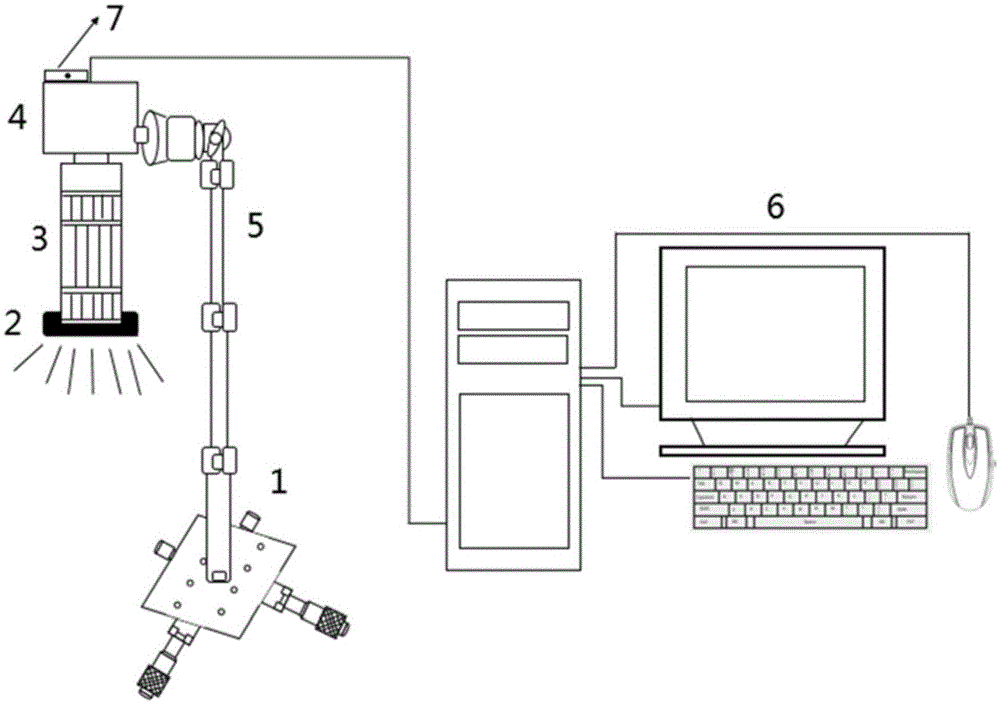
A stress testing and digital image technology, applied in the field of stress testing system based on digital image correlation method, can solve problems such as difficulty in realizing large/small-scale testing, flexible testing of full-field/local testing, complicated testing steps, and complicated data processing, etc. , to avoid the limitation of measurement stress, low test cost and high measurement accuracy
- Summary
- Abstract
- Description
- Claims
- Application Information
AI Technical Summary
Problems solved by technology
Method used
Image

Examples
Embodiment 1
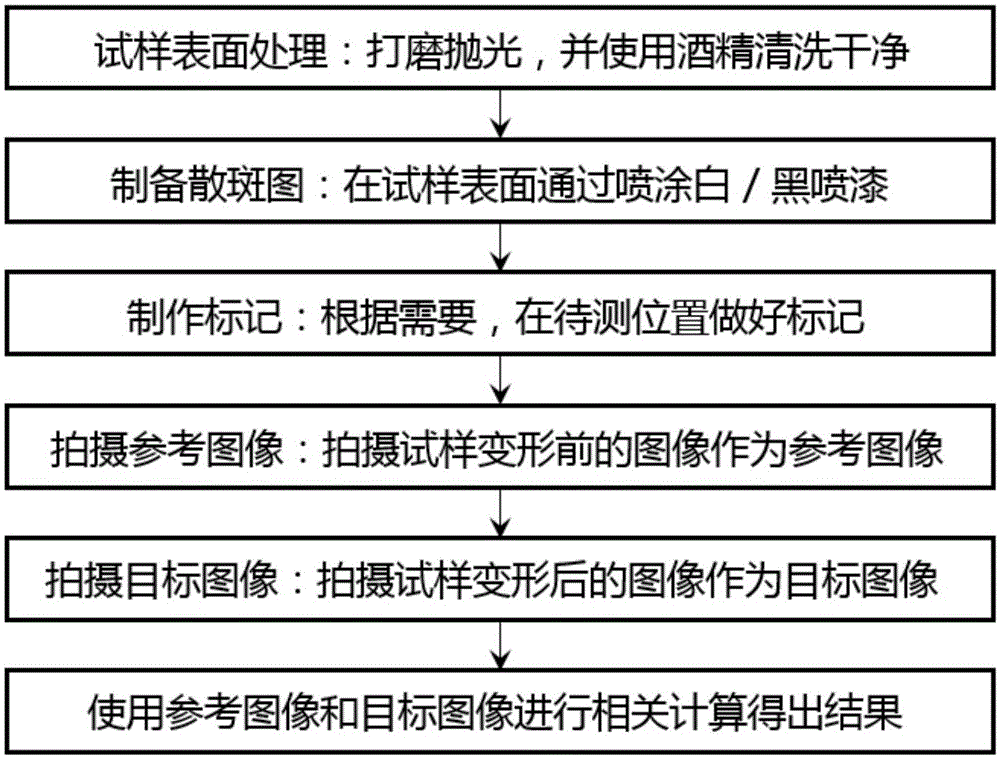
[0052] (1) The material of the tested sample is marine 945 steel, the tested sample is polished, and the surface of the sample is wiped clean with alcohol;
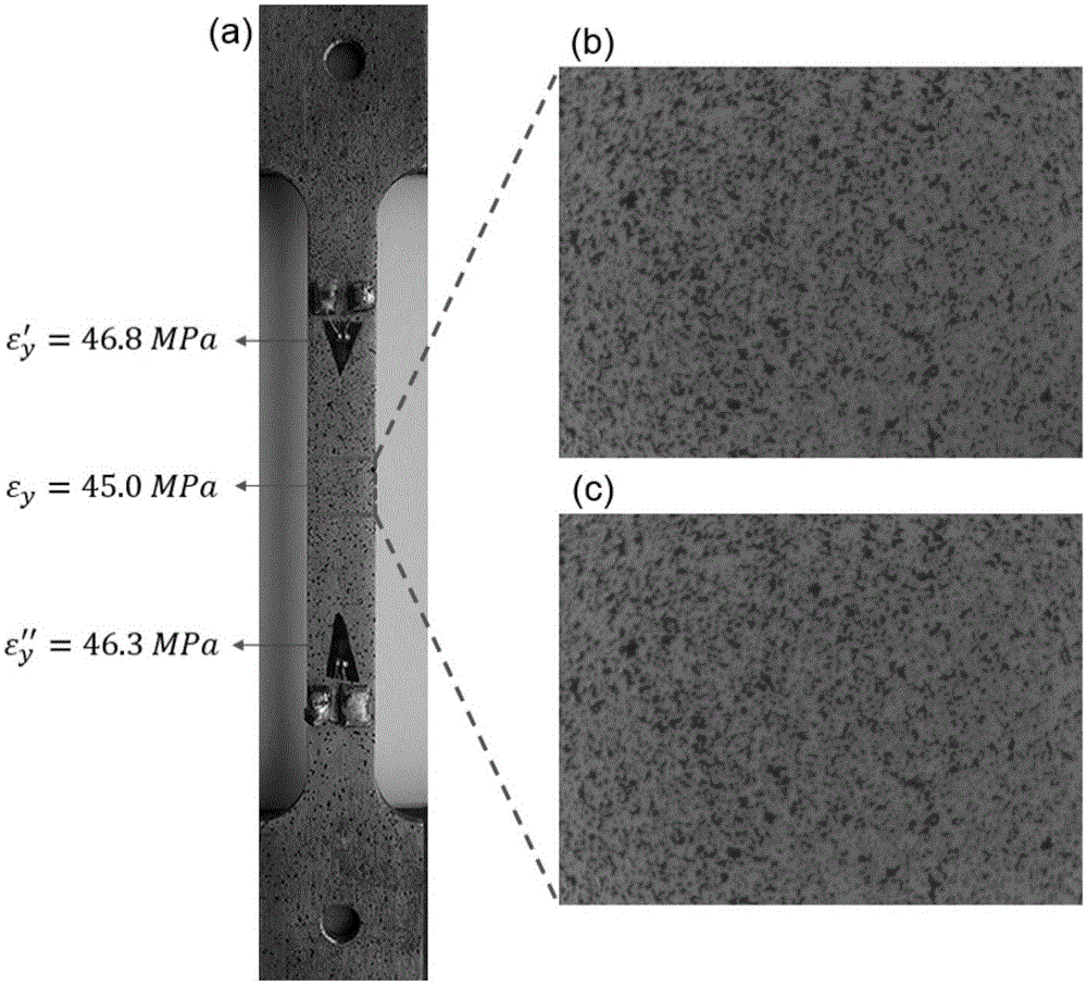
[0053] (2) By spraying white / black spray paint on the surface of the sample, an artificial speckle pattern is prepared on the surface, such as image 3 As shown in (a), the gauge length of the stretched part is 80mm, the width is 10mm, and the thickness is 2mm.;
[0054] (3) Use a small black dot on the position to be tested as a mark of the test point, so that it is convenient to quickly find the test position during the test;
[0055] (4) Adjust the position and orientation of the test system according to the mark of the measuring point, so that the digital camera can image clearly, and take the image before deformation as a reference image, such as image 3 as shown in (b);
[0056] (5) Apply a tensile load of 1kN to the tested sample, and take the deformed image as the target image in this stretched state, such as ...
Embodiment 2
[0060] (1) The material of the tested sample is T23 steel, the tested sample is polished, and the surface of the sample is wiped clean with alcohol;
[0061] (2) By spraying white / black spray paint on the surface of the sample, an artificial speckle pattern is prepared on the surface, such as Figure 4 as shown in (a);
[0062] (3) Use a small black dot on the position to be tested as a mark of the test point, so that it is convenient to quickly find the test position during the test;
[0063] (4) Adjust the position and orientation of the test system according to the measuring point marks, so that the digital camera can clearly image, and take the image before deformation as a reference image;
[0064] (5) Apply a compressive load of 20kN to the tested sample, and then release the load. The sample after deformation is as follows: Figure 4 As shown in (b), take the deformed image as the target image;
[0065] (6) Using the digital image correlation method to process the ob...
Embodiment 3
[0067] (1) with the sample after deformation in embodiment 2 as tested sample, it is fixed on the flat plane;
[0068] (2) Use a black dot on the point where the hole needs to be drilled as a new measuring point mark;
[0069] (3) Adjust the position and orientation of the test system according to the mark of the measuring point, so that the digital camera can clearly image, and take the image before drilling as a reference image, such as Figure 5 as shown in (a);
[0070] (4) Raise the digital camera by adjusting the telescopic rod of the camera support rod or adjust the rotation knob on the upper part of the camera support rod to make the digital camera and the support rod in the same line, thereby leaving enough space for drilling;
[0071] (5) According to the test requirements, use a drilling machine to drill a hole with a certain aperture and depth at the mark of the measuring point;
[0072] (6) Return the camera to its original position by adjusting the telescopic r...
PUM
| Property | Measurement | Unit |
|---|---|---|
| Resolution | aaaaa | aaaaa |
Abstract
Description
Claims
Application Information