
Combined cooling tower

A cooling tower and composite technology, which is applied in the field of cooling tower devices and composite cooling towers, can solve the problems of not being able to meet the process requirements alone, fouling on the surface of heat exchange tubes, and different temperature ranges, and achieve a wide range of application markets and prospects. The effect of saving water consumption and delaying the rate of decline

Inactive Publication Date: 2015-11-18
DONGHUA UNIV
View PDF9 Cites 13 Cited by
  • Summary
  • Abstract
  • Description
  • Claims
  • Application Information

AI Technical Summary

Problems solved by technology

Since the latent heat of vaporization of water is very large, the heat transfer coefficient outside the tube of the closed cooling tower is much larger than that of the air cooler, and the heat transfer effect is good. However, when dealing with hot water with a higher temperature, The spray water outside the tube is easy to scale on the surface of the heat exchange tube, which affects the heat transfer effect and reduces the efficiency
It can be seen that neither the finned tube dry air cooler nor the bare tube bundle closed cooling tower can meet the process requirements alone, and the temperature range for effective heat transfer is different.

Method used


Image

  • Combined cooling tower

Examples


Embodiment Construction

[0019] In order to make the present invention more comprehensible, preferred embodiments are described in detail below with accompanying drawings.

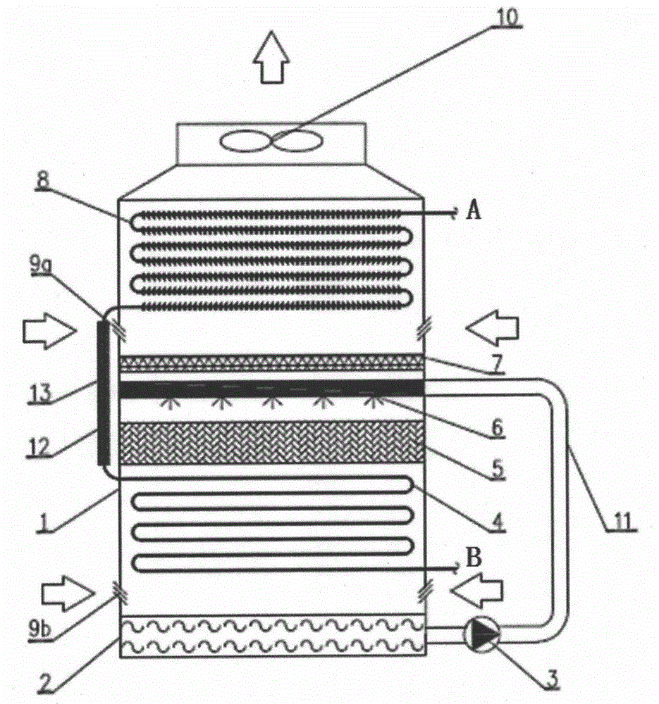
[0020] Such as figure 1 As shown, the composite cooling tower main box 1, water tank 2, spray water circulation pump 3, bare tube bundle 4, filler 5, spray equipment 6, water retaining plate 7, finned tube bundle 8, louvers 9a, louvers 9b, The induced draft fan 10, the circulating water pipe 11, the coil connecting section 12, the thermal insulation material 13 and other components are composed. In the figure, A is the hot water inlet, B is the hot water outlet, the directions of the arrows on both sides of the box body 1 are the air intake directions of the shutters 9a and 9b, and the directions of the arrows on the top of the box body 1 are the air outlet directions.

[0021] The box body 1 is made of glass fiber reinforced plastic material in the form of a cuboid, fixed on the ground by bolts, and easy to disassemble. The wat...


PUM


Abstract

The invention discloses a combined cooling tower. The combined cooling tower mainly comprises a water tank, a spraying pump, smooth tube bundles, a filler, a spray nozzle, a water baffle, fin tube bundles and an induced draft fan. Air outside the tower enters the cooling tower from a blind window at the bottom, passes through the smooth tube bundles, a filler section and the fin tube bundles sequentially from bottom to top and is discharged to surroundings by the induced draft fan at the top after heat is carried away. High temperature fluids firstly pass through the fin tube bundles to be pre-cooled from top to bottom, then enter the smooth tube bundles to be subjected to evaporative cooling and flow out of the cooling tower after being cooled to required temperature. Depressing angles of the blind window are arranged in positions of four sides of a wall surface of a box body below the fin tube bundles so that air can enter and be mixed with the air which enters from the blind window at the bottom and then moves upwards for cooling high temperature water in the fin tube bundles, and corrosion of fin tubes is delayed while the cooling efficiency is increased. The filler section is arranged for evaporative cooling, the contact area of air and sprayed water is increased, heat exchange time is prolonged, and heat exchange efficiency is increased. The temperature difference of the combined cooling tower is greater than that of a common cooling device during cooling of high temperature water, energy saving performance and water saving performance are remarkable, the structure is compact, and usage is convenient.

Description

technical field [0001] The invention relates to a composite cooling tower, in particular to a cooling tower device combining dry cooling and wet cooling, and belongs to the application field of cooling devices. Background technique [0002] Energy is the foundation of social development, the driving force and source of economic development, and the guarantee for improving people's living standards. At present, my country still faces problems such as irrational distribution of energy structure, low efficiency, and development and production that cannot keep up with consumption levels. During the "Twelfth Five-Year Plan" period, my country put forward the energy strategic deployment of adhering to energy saving, emission reduction and sustainable development. In terms of industrial water consumption, my country's industrial water consumption mainly faces problems such as uneven distribution, continuous growth of water consumption, low efficiency, and serious pollution. In orde...

Claims


Application Information

Patent Timeline
IPC IPC(8): F28C1/14F28F1/00F28F1/24F28F19/00
Inventor 周亚素李进庄亚男白羽丰潘科费一超
Owner DONGHUA UNIV
Learn More