Lateral high-voltage device and manufacturing method thereof

A technology of lateral high voltage and manufacturing method, which is applied in semiconductor/solid-state device manufacturing, semiconductor devices, electrical components, etc., and can solve problems such as limited application and rise in on-resistance

Inactive Publication Date: 2015-11-18
UNIV OF ELECTRONICS SCI & TECH OF CHINA
View PDF4 Cites 5 Cited by
  • Summary
  • Abstract
  • Description
  • Claims
  • Application Information

AI Technical Summary

Problems solved by technology

When the device is used in high-voltage applications, the on-resistance rises sharply, which limits the application of high-voltage devices in high-voltage power integrated circuits, especially circuits that require low conduction loss and small chip area
In order to overcome the problem of high on-resistance, J.A. APPLES and others proposed RESURF (ReducedSURfaceField) to reduce the surface field technology, which is widely used in high-voltage devices. Although the on-resistance is effectively reduced, the breakdown voltage and on-resistance The contradictory relationship still needs to be further improved

Method used


Image

  • Lateral high-voltage device and manufacturing method thereof
  • Lateral high-voltage device and manufacturing method thereof
  • Lateral high-voltage device and manufacturing method thereof

Examples


Embodiment 1

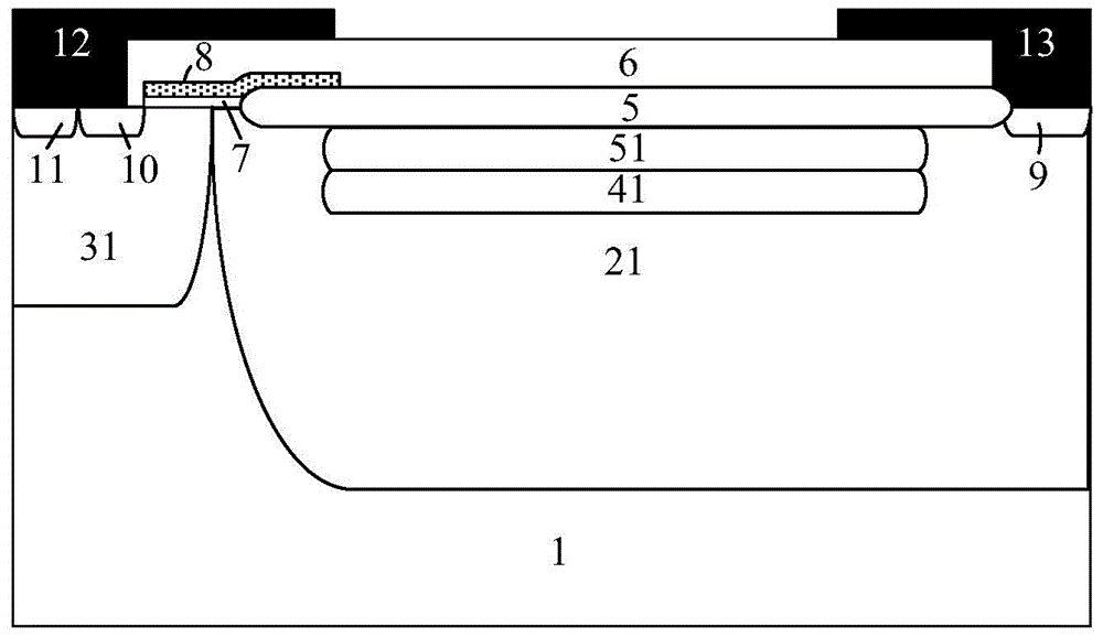
[0045] figure 2 A cross-sectional view of a lateral high-voltage device structure provided in this embodiment.

[0046] A lateral high-voltage device, the cell structure of which includes a first conductivity type semiconductor substrate 1; a second conductivity type semiconductor first drift region 21 arranged on the right side of the first conductivity type semiconductor substrate 1, the second conductivity type semiconductor The upper surface of the first drift region is flush with the upper surface of the first conductivity type semiconductor substrate 1; the first body region of the first conductivity type semiconductor disposed on the left side of the first conductivity type semiconductor substrate 1, the first conductivity type semiconductor The upper surface of the first body region is flush with the upper surface of the semiconductor substrate of the first conductivity type and connected to the first drift region of the semiconductor of the second conductivity type; ...

Embodiment 2

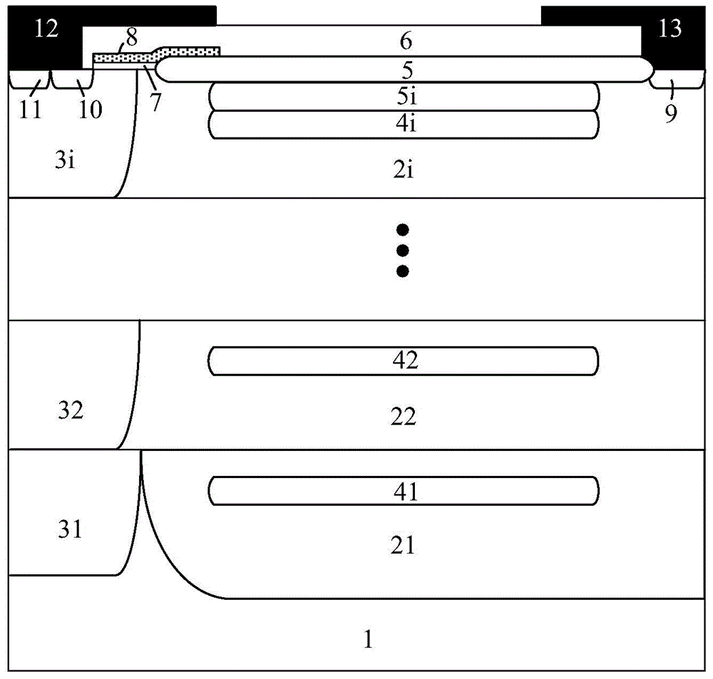
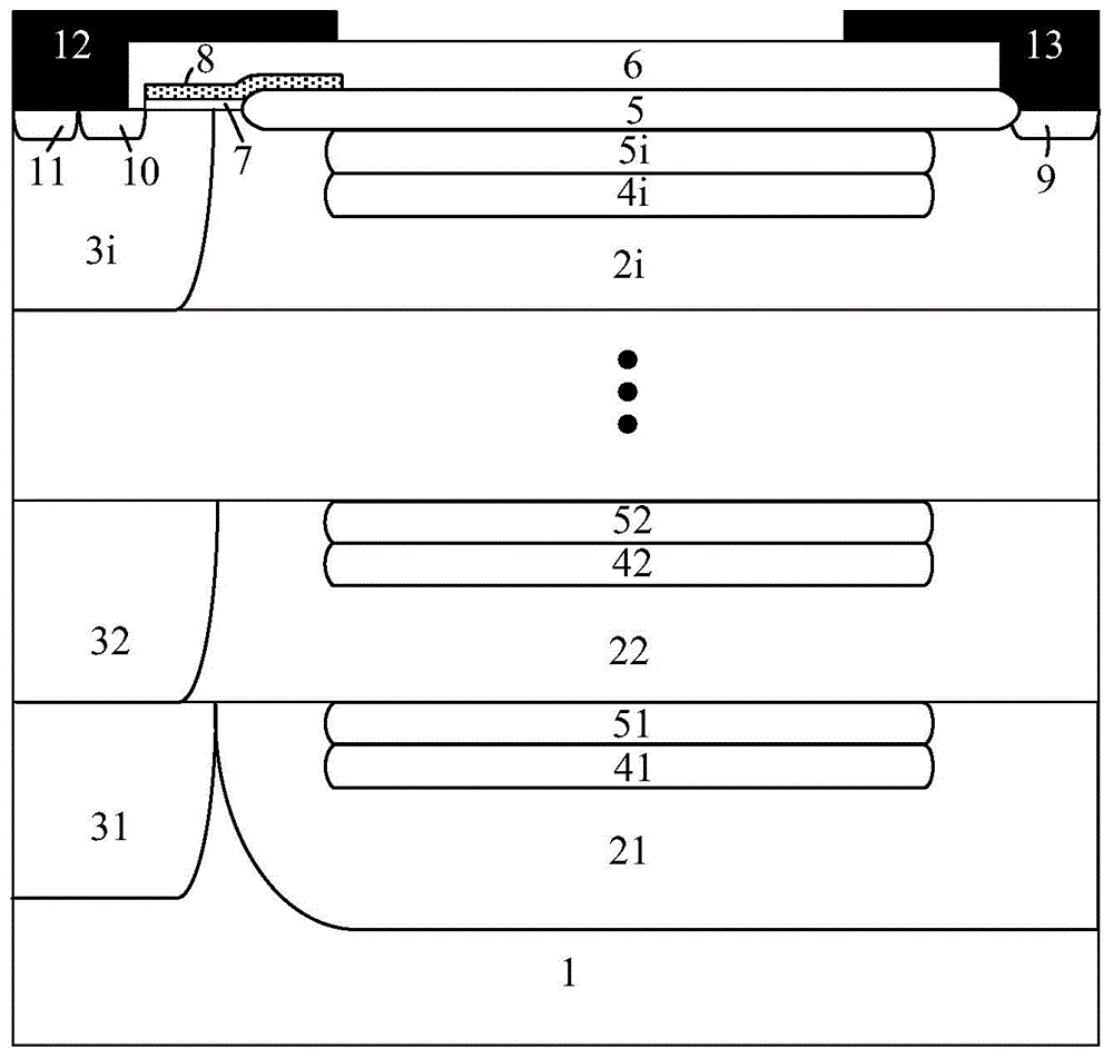
[0050] Such as image 3 As shown, the difference between this embodiment and Embodiment 1 is that: each second conductivity type semiconductor sub-drift region 21, 22 . . . The doped layers are respectively 51, 52...5i in turn.

Embodiment 3

[0052] Such as Figure 4 As shown, this embodiment is basically the same as Embodiment 2, the difference is that it also includes a buried oxide layer 3 and a semiconductor substrate 2 of the second conductivity type, and the buried oxide layer 3 is arranged under the semiconductor substrate 1 of the first conductivity type. , the second conductivity type semiconductor substrate 2 is disposed under the buried oxide layer 3 . Its working principle and effect are the same as those in Embodiment 2.


PUM


Abstract

The invention provides a lateral high-voltage device and a manufacturing method thereof. A device cell structure comprises a first conducting-type semiconductor substrate and drift regions of a second conducting-type semiconductor, wherein a plurality of sub-drift regions of the second conducting-type semiconductor are sequentially stacked on the drift regions of the second conducting-type semiconductor from bottom to top. The method comprises the following steps: injecting the first drift region of the second conducting-type semiconductor into the first conducting-type semiconductor substrate by an ion implantation technology; sequentially forming other sub-drift regions of the second conducting-type semiconductor by an epitaxy technique; and forming reduced-field layers of the first conducting-type semiconductor and heavily-doped layers of the second conducting-type semiconductor in the sub-drift regions of the second conducting-type semiconductor by ion implantation. According to the lateral high-voltage device, a traditional drift region is manufactured into a structure of superposing a plurality of layers of drift regions, so that a nearest low-resistance conductive path is formed in each sub-drift region; the on-resistance can be reduced; and in a closed state, the reduced-field layer in each drift region exhausts each drift region in an assist manner, so that the breakdown voltage of the device is improved.

Description

technical field [0001] The invention relates to the technical field of semiconductor power devices, and relates to a lateral high voltage device and a manufacturing method thereof. Background technique [0002] Lateral high-voltage devices are an essential part of the development of high-voltage power integrated circuits. High-voltage power devices require high breakdown voltage, low on-resistance and low switching loss. To achieve a high breakdown voltage of a lateral high voltage device, the drift region used to withstand the voltage is required to have a long size and low doping concentration, but in order to meet the low on-resistance of the device, the drift region as a current channel is required to have a high doping concentration. In the design of power LDMOS (LatralDouble-diffusedMOSFET) devices, breakdown voltage (BreakdownVoltage, BV) and specific on-resistance (Specificon-resistance, R on,sp ) has a contradictory relationship. When the device is used in high-v...

Claims


Application Information

Patent Timeline
Patent Type & Authority Applications(China)
IPC IPC(8): H01L29/78H01L29/06H01L21/336
CPCH01L29/7816H01L29/06H01L29/66681
Inventor 乔明代刚王裕如周锌何逸涛张波
Owner UNIV OF ELECTRONICS SCI & TECH OF CHINA
Why Eureka
Try Eureka