Method for producing semi-metallurgical metal composite tube through electric resistance welding
A metal composite pipe and semi-metallurgical technology, applied in the direction of resistance welding equipment, metal processing, metal processing equipment, etc., can solve the problems of high cost and complicated manufacturing process, and achieve the effect of easy disassembly, low input cost and convenient wiring
- Summary
- Abstract
- Description
- Claims
- Application Information
AI Technical Summary
Problems solved by technology
Method used
Image
Examples
Embodiment 1
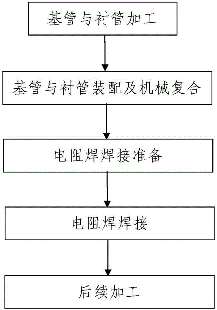
[0040] Such as figure 1 A method of producing semi-metallurgical metal clad pipes shown by resistance welding comprises the following steps:
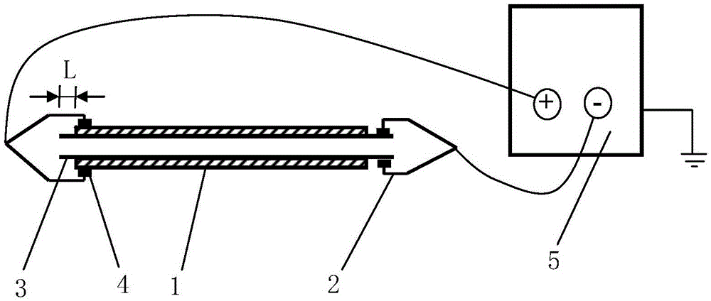
[0041] Step 1, base pipe and liner processing: respectively process the base pipe 1 and the liner 3 of the produced metal composite pipe, the length of the liner 3 is greater than the length of the base pipe 1;
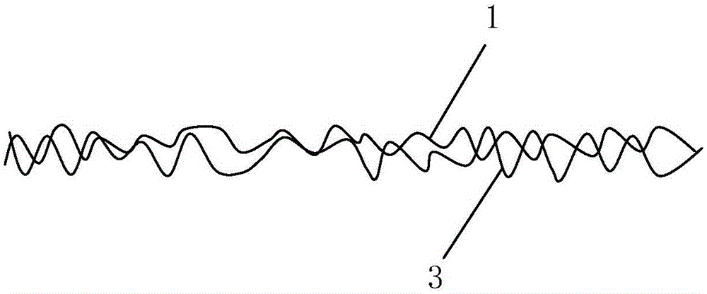
[0042] Step 2: Base pipe and liner assembly and mechanical compounding: the liner 3 described in step 1 is coaxially loaded into the base pipe 1, and both ends of the liner 3 are extended to the outside of the base pipe 1; The bimetallic pipe mechanical composite method combines the base pipe 1 and the liner pipe 3 into one body to form a mechanical metal composite pipe; the segments at both ends of the liner pipe 3 protruding to the outside of the base pipe 1 are all overhanging sections; The microstructure of the substrate-liner contact surface in mechanical metal composite pipes, see image 3 ;
[0043] Step 3. Preparatio...
Embodiment 2
[0077] In this embodiment, the difference from Embodiment 1 is that the finished semi-metallurgical metal composite pipe has a specification of Φ610×(20+2) mm; the material of the base pipe 1 in step 1 is L485 carbon steel, and The outer diameter of the tube 1 is Φ610mm, the length is 3m and its wall thickness is 20mm; the material of the liner 3 is 316L stainless steel and its wall thickness is 2mm, the outer diameter of the liner 3 is Φ560mm and its length is 3.3 m; L=150mm in the second step; the welding current in the fourth step is 8000A and the welding time is 400ms.
[0078] In this embodiment, the remaining method steps and parameters are the same as those in Embodiment 1.
[0079] In this example, the results of the endoscopic inspection, bonding strength inspection, metallographic inspection of the substrate-lining interface, radiographic flaw detection, and hydraulic test of the processed and formed semi-metallurgical metal composite pipe are all qualified, and the ...
Embodiment 3
[0081] In this embodiment, the difference from Embodiment 1 is that the finished semi-metallurgical metal composite pipe has a specification of Φ76×(7+2) mm; the base pipe 1 in step 1 is made of 20G carbon steel, and the base The outer diameter of the tube 1 is Φ76mm, the length is 10m and its wall thickness is 7mm; the material of the liner 3 is 2205 duplex stainless steel and its wall thickness is 2mm, the outer diameter of the liner 3 is Φ60mm and its length It is 10.16m; L=80mm described in the second step; the welding current in the fourth step is 14500A and the welding time is 200ms.
[0082] In this embodiment, the remaining method steps and parameters are the same as those in Embodiment 1.
[0083] In this example, the results of the endoscopic inspection, bonding strength inspection, metallographic inspection of the substrate-lining interface, radiographic flaw detection, and hydraulic test of the processed and formed semi-metallurgical metal composite pipe are all qu...
PUM
| Property | Measurement | Unit |
|---|---|---|
| length | aaaaa | aaaaa |
| length | aaaaa | aaaaa |
| thickness | aaaaa | aaaaa |
Abstract
Description
Claims
Application Information
 - R&D
- Intellectual Property
- Life Sciences
- Materials
- Tech Scout
- Unparalleled Data Quality
- Higher Quality Content
- 60% Fewer Hallucinations
Browse by: Latest US Patents, China's latest patents, Technical Efficacy Thesaurus, Application Domain, Technology Topic, Popular Technical Reports.
© 2025 PatSnap. All rights reserved.Legal|Privacy policy|Modern Slavery Act Transparency Statement|Sitemap|About US| Contact US: help@patsnap.com


