
Machining method of laser marking machine

A laser marking machine and processing method technology, applied in typewriters, printing and other directions, can solve the problems of difficult to unify product appearance processing effect, single processing method mode, poor processing flexibility, etc., to shorten the transition time, flexible processing method, three-dimensional strong effect

Active Publication Date: 2015-11-25
GBOS LASER INC
View PDF6 Cites 5 Cited by
  • Summary
  • Abstract
  • Description
  • Claims
  • Application Information

AI Technical Summary

Problems solved by technology

[0003] Most of the existing laser marking machines are 2D plane marking processing, and the marking effect is relatively rigid, which cannot fully reflect the real effect of materials worn on people or mannequins. When double-sided marking is required, it is often necessary to add After the marking on one side is completed, the material must be turned over, flattened, and the station is adjusted twice before the laser marking operation on the next side can be carried out. The process is cumbersome and the processing efficiency is low. And the secondary calibration stations are all manually operated, and the processing accuracy is not high, which makes it difficult to uniform the processing effect of the product appearance, the quality is uneven, and the yield rate is low. In addition, the processing method of this laser marking machine is single. Poor flexibility

Method used


Image

  • Machining method of laser marking machine
  • Machining method of laser marking machine
  • Machining method of laser marking machine

Examples


Embodiment Construction

[0030] The present invention will be further described below in conjunction with accompanying drawing of description:

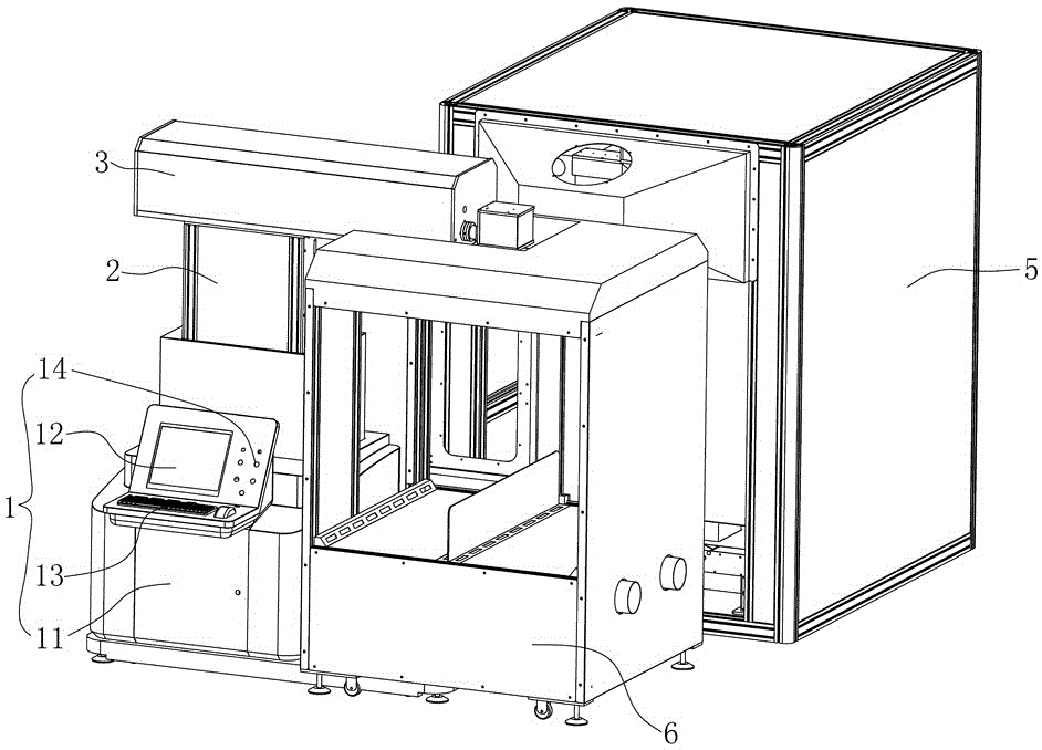
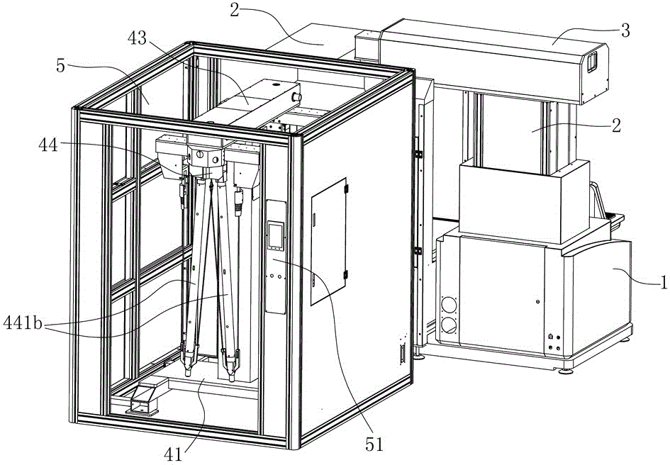
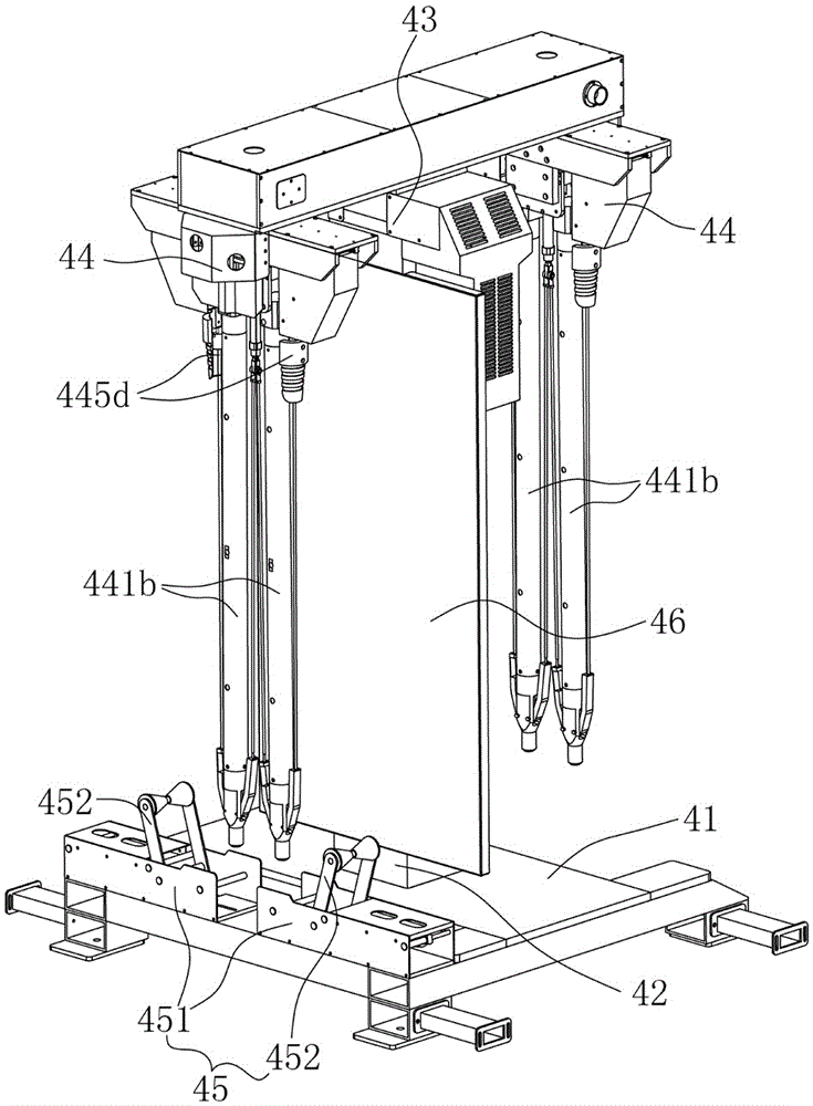
[0031] Such as Figure 1-8 As shown, the present invention relates to a processing method of a laser marking machine. The laser marking machine is composed of a control unit 1 and an optical path assembly 3 arranged on the control unit 1 through a lift table 2. The rear of one end of the optical path assembly 3 is A 3D vertical support and rotation device 434 is provided, and the 3D vertical support and rotation device 434 includes a base frame 41, a column 42 arranged on the base frame 41, a rotation device 43 located at the top of the column 42, and two sides of the rotation device 43. The support tube device 44 at the end and the expansion mechanism 45 arranged under one of the support tube devices 44, each of the support tube devices 44 includes a support tube part 441, and the 3D vertical support and rotation device 434 is also equipped with a protective...


PUM


Abstract

The invention relates to the technical field of laser marking, and discloses a machining method of a laser marking machine. The laser marking machine is composed of a control unit and a light path assembly arranged on the control unit through a lifting table. A 3D vertical supporting rotating device is arranged behind one end of the light path assembly and comprises a bottom frame, a stand column arranged on the bottom frame, a rotating device arranged at the top end of the stand column, pipe expanding devices arranged at the two ends of the rotating device and an expanding mechanism arranged below one pipe expanding device. Each pipe expanding device comprises a pipe expanding part. The machining method of the laser marking machine comprises the first step of equipment preparing, the second step of material matching, the third step of laser machining, the fourth step of material replacing and the fifth step of resetting shutdown. According to the machining method of the laser marking machine, it is guaranteed that the appearance effect of finished products is uniform, the product yield is increased, the machining method is simplified, and the machining efficiency is improved as a whole.

Description

technical field [0001] The invention relates to the technical field of laser marking, in particular to a 3D vertical processing surface formed of materials to be processed through a supporting tube device, and the height adjustment of the lifting platform is used to realize the 3D marking operation of the optical path assembly, and a switching part is adopted The processing method of the laser marking machine that switches the 2D / 3D marking mode. Background technique [0002] Laser laser washing process is a pollution-free, non-washing, green and environmentally friendly process. This process uses laser equipment to laser-etch the yarn on the surface of jeans. The yarn floating on the surface will undergo physical fading reaction due to high temperature. , so as to form the washing pattern we need. This process can not only process ready-made jeans, but also process large-area denim, cut pieces and other clothing fabrics. At the same time, it can also laser different pattern...

Claims


Application Information

Patent Timeline
IPC IPC(8): B41J3/407B41J2/435
Inventor 刘文
Owner GBOS LASER INC
Learn More