Underground station constructed by prefabricated parts and construction method thereof

A technology of prefabricated components and underground stations, applied in infrastructure engineering, buildings, artificial islands, etc., can solve problems such as slowing down construction speed, reducing construction efficiency, longitudinal reinforcement deviation, etc., to reduce the impact of noise and vibration, soil Effect of small disturbance and flexible construction operation

Active Publication Date: 2015-11-25
山东轨道交通勘察设计院有限公司 +1
View PDF8 Cites 22 Cited by
  • Summary
  • Abstract
  • Description
  • Claims
  • Application Information

AI Technical Summary

Problems solved by technology

However, the application of the existing prefabricated component assembly technology in subway stations still has some problems that need to be improved, such as the combination process of prefabricated components and the improvement of construction machinery.
After the construction of existing underground stations is completed, it is generally necessary to use cast-in-place concrete to make structural columns. This method is firstly difficult to construct, and secondly, the longitudinal reinforcement of the cast-in-place concrete structure will be displaced, resulting in dangerous situations. At the same time, the cast-in-place concrete structure has complicated procedures, which slows down the construction speed
In the existing construction of underground stations using shield machines, the construction of shield machines generally requires relatively high thickness of the covering soil, and the shield construction has a great impact on the disturbance of the surrounding soil
[0003] Chinese patent CN103967050A discloses a construction system of a subway station, which consists of an enclosure structure and a main structure. The guide wall steel formwork system is used for guide wall construction, the support beam steel formwork system is used for support beam construction, and the side wall trolley is used for side wall construction. Construction, using floor trolleys for floor construction, this patent still requires construction guide walls, underground diaphragm walls and reinforced concrete supports, which will greatly increase the construction process and reduce construction efficiency; The construction method of this patent is to use the corresponding components required for the prefabricated subway station in the factory, and then transport them to the construction site for the cover excavation of the subway station. Although the patent uses prefabricated laminated panels as the roof formwork, it saves the time for formwork support and removal. However, during the construction process, structures such as retaining piles and column piles need to be prefabricated. After the prefabrication is completed, the entire subway station still needs to be excavated at the construction site. The construction process is complicated and will inevitably affect the construction efficiency.
[0004] Chinese patent CN104762990A discloses a method for building a modular subway station, wherein the whole station structure is divided into prefabricated floor components, roof prefabricated components and side wall prefabricated components; Chinese patent CN104153389A discloses the construction of prefabricated assembled subway stations method, the prefabricated components are also composed of prefabricated floor components, roof prefabricated components and side wall prefabricated components that can be assembled. In these two patents, it is necessary to assemble the divided parts in the overall construction process of the subway station. The construction speed It cannot be guaranteed, and at the same time, the assembled and divided components during the entire construction process cannot guarantee the stability of the assembled structure

Method used


Image

  • Underground station constructed by prefabricated parts and construction method thereof
  • Underground station constructed by prefabricated parts and construction method thereof
  • Underground station constructed by prefabricated parts and construction method thereof

Examples


Embodiment Construction

[0052] The present invention will be further described below in conjunction with the accompanying drawings and embodiments.

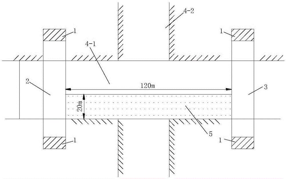
[0053] Such as figure 1 As shown, the underground station 5 is arranged on the side of the road 4-1 at the construction site of the underground station, and the other road 4-2 at the intersection is not arranged. First, the shaft 1 is constructed on both sides of the road at the two ends of the station, and the construction is completed. After the vertical shaft 1, the construction of the starting tunnel 2 and the receiving tunnel 3 is carried out. After the completion of the two constructions, a strip track is laid along the axial direction of the tunnel in the starting tunnel 2 and the receiving tunnel 3 (the strip track refers to the tunnel from the shaft to the construction section). The laid track is used to transport prefabricated components in the early stage), and the rectangular pipe-jacking strip track is laid along the axis of the station at ...


PUM


Abstract

The invention discloses an underground station constructed by prefabricated parts and a construction method thereof. The underground station comprises an upper station layer and a lower station layer; the upper station layer and the lower station layer are both formed by assembling a plurality of prefabricated parts, the lower station layer is communicated with the upper station layer, upper and lower station layer stairways are arranged at the communicating position, and the lower station layer is provided with a platform; the upper station layer is communicated with the ground, and a plurality of ground stairways communicated with the ground are arranged in the upper station layer. The lower station layer and the upper station layer are constructed in sequence, stiffening rib steel structures are dismantled after assembly of the prefabricated parts is completed, and an underground station space structure is formed; a top plate of the lower station layer and a bottom plate of the upper station layer are connected through bolts, pouring and leveling treatment is performed on bottom plates of the two layers, combined structure columns in the station are bound, and concrete is poured for reinforcement; then the station is decorated to complete station construction. The method has the advantages that construction is flexible and rapid, small-buried depth construction can be performed, influences on traffic and environment are small, and industrial production can be achieved.

Description

technical field [0001] The invention belongs to the field of underground construction engineering, in particular to an underground station built with prefabricated components and a construction method thereof. Background technique [0002] Traditional subway stations are often constructed by open-cut method, cover-excavation method or shield tunneling method. These subway station construction methods have certain defects and can only be applied to certain special geological or environmental conditions. With the advancement of underground engineering construction technology and new material manufacturing technology, a new method of using prefabricated components to construct subway stations has emerged. This method has the characteristics of less environmental pollution, no obstruction to traffic, and fast construction speed, and has broad development prospects. However, the application of the existing prefabricated component assembly technology in subway stations still has s...

Claims


Application Information

Patent Timeline
Patent Type & Authority Applications(China)
IPC IPC(8): E21D9/00E02D29/045
Inventor 王国富路林海王德超
Owner 山东轨道交通勘察设计院有限公司
Why Eureka
Try Eureka