Asymmetric permanent-magnet bias axial magnetic bearing

A technology of axial magnetic bearing and permanent magnet bias, which is applied in the direction of shafts and bearings, bearings, mechanical equipment, etc., can solve the problems of increasing copper loss of windings, controlling power amplifier loss, large bias current, and increasing control current, etc., to achieve Effects of reducing winding copper loss and controlling power amplifier loss, increasing rotor mode and speed, and reducing static bias current

Active Publication Date: 2015-11-25
BEIHANG UNIV
View PDF8 Cites 26 Cited by
  • Summary
  • Abstract
  • Description
  • Claims
  • Application Information

AI Technical Summary

Problems solved by technology

However, when there is an unbalanced force on both ends of the axial direction, such as a blower, the bias current that accounts for the main component of the coil current is relatively large, which increases the copper loss of the winding and the loss of the control power amplifier.
There are also some radial and axial integrated magnetic bearings with permanent magnet bias. Although the volume is smaller and the axial length is shortened, there is a problem of radial and axial coupling.
Due to the

Method used


Image

  • Asymmetric permanent-magnet bias axial magnetic bearing
  • Asymmetric permanent-magnet bias axial magnetic bearing
  • Asymmetric permanent-magnet bias axial magnetic bearing

Examples


Embodiment Construction

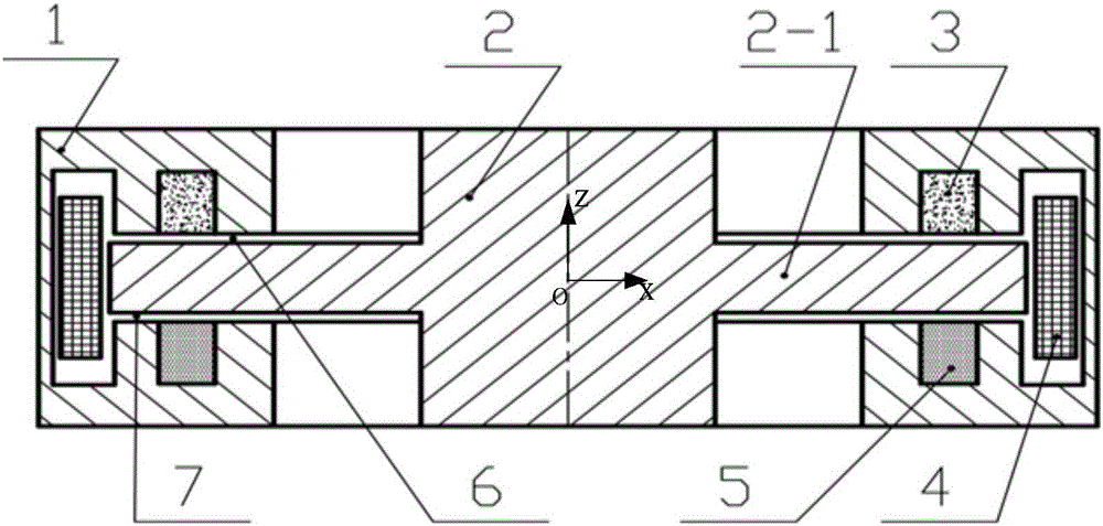
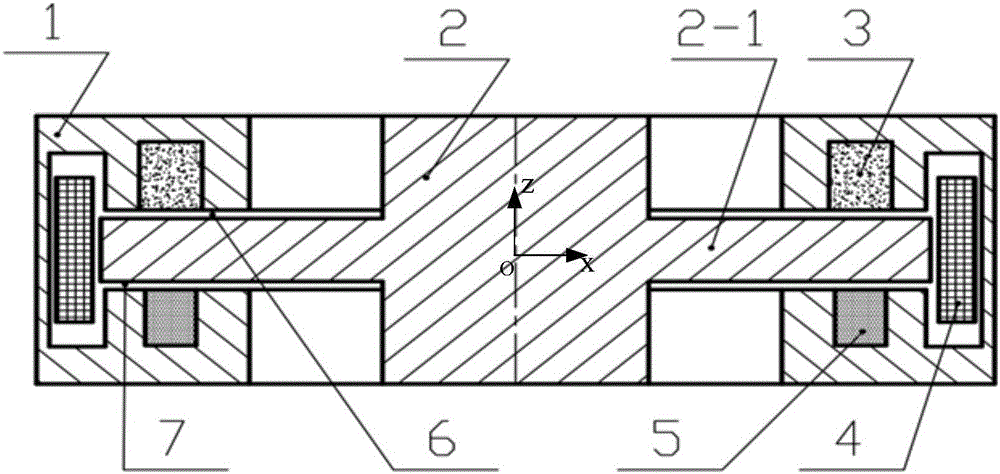
[0015] Such as figure 1 As shown, it is an asymmetric permanent magnet bias axial magnetic bearing composed of two permanent magnets with the same shape and size but different materials, which is one of the technical solutions of the present invention, which is the basic form of the present invention. It consists of stator core 1, rotor core 2 with thrust disc, first permanent magnet 3, second permanent magnet 5 and excitation coil 4. The double E-shaped stator cores form four stator poles in the positive and negative directions of the magnetic bearing Z, and two stator poles in the positive and negative directions of Z. Between the two stator poles in the Z positive direction and the Z negative direction are two annular permanent magnets with the same shape and size but different materials, which can generate different static bearing capacities in the two axial directions while providing bias magnetic density. . Two permanent magnets with different coercive forces are sele...


PUM


Abstract

The invention relates to an asymmetric permanent-magnet bias axial magnetic bearing. The asymmetric permanent-magnet bias axial magnetic bearing is composed of a stator iron core, a rotor iron core with a thrust disc, permanent magnets and an exciting coil. The double-E-shaped stator iron core forms four stator magnetic poles in Z positive and negative directions of the magnetic bearing, and two stator magnetic poles are disposed in each of the Z positive and negative directions. The two stator magnetic poles in each of the Z positive and negative directions are two annular permanent magnets different in magnetomotive force and can produce different static carrying forces in the two axial directions while providing bias magnetic flux density. According to the asymmetric permanent-magnet bias axial magnetic bearing, the asymmetric annular permanent magnets different in magnetomotive force are used in the Z positive and negative directions for producing different static carrying forces in the two axial directions while providing bias magnetic fields, so that static bias current is greatly reduced; the exciting coil is disposed in radial space of the double-E-shaped stator iron core, and accordingly axial space is saved, and unnecessary radial force is prevented from being produced; the asymmetric permanent-magnet bias axial magnetic bearing has the advantages of being reliable in performance, convenient to control and low in loss.

Description

technical field [0001] The invention relates to a non-contact magnetic suspension bearing, in particular to an asymmetrical permanent magnetic bias axial magnetic bearing, which can be used as a non-contact support for rotating parts in mechanical equipment such as motors and molecular pumps. Background technique [0002] Magnetic suspension bearings are divided into passive magnetic bearings, pure electromagnetic active magnetic bearings and hybrid magnetic suspension bearings with permanent magnetic bias and electromagnetic control. Although the passive magnetic bearing has low power consumption, it is unstable; the pure electromagnetic magnetic bearing uses large current and high power consumption; the hybrid magnetic suspension bearing with permanent magnetic bias and electromagnetic control, the magnetic field generated by the permanent magnet bears the main bearing capacity, The electromagnetic field provides auxiliary adjustment bearing capacity, so this kind of beari...

Claims


Application Information

Patent Timeline
IPC IPC(8): F16C32/04
Inventor 房建成任小均韩邦成乐韵刘刚
Owner BEIHANG UNIV
Why Eureka
Try Eureka