Static state high efficient generators and application thereof

A technology of generators and generator sets, which is applied in the direction of electrical components, electromechanical devices, etc., and can solve the problems of high cost, popularization and promotion

Inactive Publication Date: 2015-11-25
张炳全
View PDF0 Cites 3 Cited by
  • Summary
  • Abstract
  • Description
  • Claims
  • Application Information

AI Technical Summary

Problems solved by technology

[0002] The existing generators are basically rotary generators, which are divided into rotating magnetic field type and rotating armature type; solar photovolt...

Method used


Image

  • Static state high efficient generators and application thereof
  • Static state high efficient generators and application thereof
  • Static state high efficient generators and application thereof

Examples


Embodiment 1

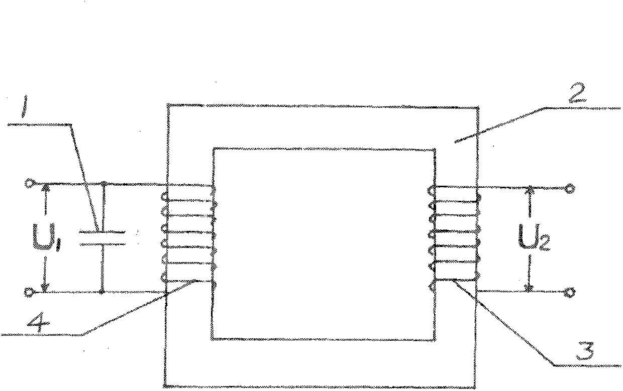
[0040] Example 1, such as figure 1 The parallel resonant static generator shown in the figure: a closed magnetic circuit is formed by an iron core (2), and a resonant capacitor (1) with adjustable capacitance is connected in parallel at both ends of the input coil (4). u 1 , the input terminal is in a parallel resonance state, the total current passing through the parallel circuit is very small, but the branch current passing through the capacitor and coil is very large, and the output coil (3) generates a terminal voltage U through electromagnetic induction 2 , to output power externally.

Embodiment 2

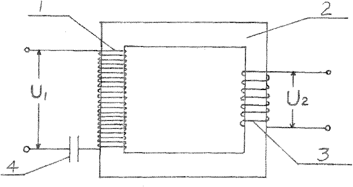
[0041] Example 2, such as figure 2 The series resonant static generator shown in the figure: the iron core (2) constitutes a closed magnetic circuit, one end of the input coil is connected in series with a resonant capacitor (4) with adjustable capacitance, and the number of turns of the input coil (1) is large, which is Many times the primary coil of the transformer with the same capacity and voltage. When working, the input circuit is in a series resonance state, and the reactance is zero. It only needs to input the AC low voltage U1 to maintain a small current, and the two ends of the output coil (3) can Induce the rated voltage U 2 , output rated electric power.

Embodiment 3

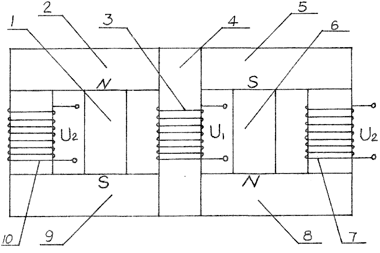
[0042] Example 3, such as image 3 The shown left and right alternating closed permanent magnet static generator: the input coil (3) is set on the core column (4) to form a central alternating electromagnet; the permanent magnet (1) with the N pole upward and the permanent magnet with the S pole upward (6) It is located on the left and right sides of the central electromagnet, and the output coils (7) and (10) are sleeved on the iron core and arranged on both sides of the left and right permanent magnets, and cooperate with the yokes (2), (5), (8), (9 ) to form 4 closed magnetic circuits; when working, the input coil is connected to the AC voltage U 1 The generated alternating magnetic flux attracts and closes alternately with the permanent magnets of the opposite sex on the left and right sides, and the permanent magnetic flux repelling the same sex as the alternating electromagnetic flux in the center can only pass through the iron core of the adjacent output coil to form a ...


PUM


Abstract

The invention relates to three types of static state high efficient generators. The three types of novel generators have no rotary movement parts because the generators are transformed and innovated based on transformers. In the static state generators, closed magnetic circuits are mainly formed by iron cores. Input coils and output coils respectively sleeve two iron core columns. In order to achieve the purpose that an output electric power is greater than an input electric power, the input coils of the static state generators are in parallel with resonant capacitors and in series with the resonant capacitor, and the mode of alternate absorption and closure of an alternate electromagnetic flux generated by the input coils and fixed different magnetic poles is employed, and the static state generators match up a rechargeable battery, an inverter, an intelligent controller and a rectifier to form an independent static state generation system. By using the static state high efficient generators, the non-pollution and zero discharge can be achieved, and inexhaustible electric energy can be supplied for various electric devices which need the electric energy.

Description

technical field [0001] The invention belongs to the field of generators and transformers. Background technique [0002] The existing generators are basically rotary generators, which are divided into rotating magnetic field type and rotating armature type; solar photovoltaic cells are a kind of static power generation, but they are affected by weather, time period and environment, and their high cost is not conducive to popularization and promotion . Contents of the invention [0003] The purpose of the invention is to provide three kinds of static high-efficiency generators whose output electric energy is much greater than the input electric energy. [0004] Another object of the present invention is to provide a variety of land, sea and air electric transportation tools that use static high-efficiency generators as power sources. [0005] The three kinds of static high-efficiency generators provided by the present invention belong to a general inventive concept, and ar...

Claims


Application Information

Patent Timeline
IPC IPC(8): H02K53/00
Inventor 张炳全
Owner 张炳全
Why Eureka
Try Eureka