Electric quantity isolation sensor

A sensor and power technology, applied in voltage/current isolation, adjustment of electrical variables, instruments, etc., can solve the problems of high technical difficulty, low reliability, poor product temperature performance, etc., to achieve high isolation, improve accuracy and reliability. Effect

Active Publication Date: 2015-11-25
MIANYANG WEIBO ELECTRONICS
View PDF4 Cites 5 Cited by
  • Summary
  • Abstract
  • Description
  • Claims
  • Application Information

AI Technical Summary

Problems solved by technology

[0003] Electromagnetic isolation pulse width modulation (PulseWidthModulation, PWM) technology transmits pulse width signals, and the transmission accuracy is hardly affected by leakage inductance. It should be very suitable for high isolation monitoring occasions. However, for a long time, high-precision PWM modulation The demodulation technology is very difficult, the temperature performance of the product is poor, and the reliability is low, especially under the premise of cost control, so that there are very few high-precision industrial products successfully applied to mass production at home and abroad.
For a long time, the domestic railway industry has mainly relied on the introduction of sensors from foreign manufacturers. In recent years, although some domestic manufacturers have introduced DC high-voltage and high-isolation products, the measurement accuracy is only 0.5, and there is still a certain gap between them and foreign products.

Method used


Image

  • Electric quantity isolation sensor
  • Electric quantity isolation sensor

Examples


Embodiment 1

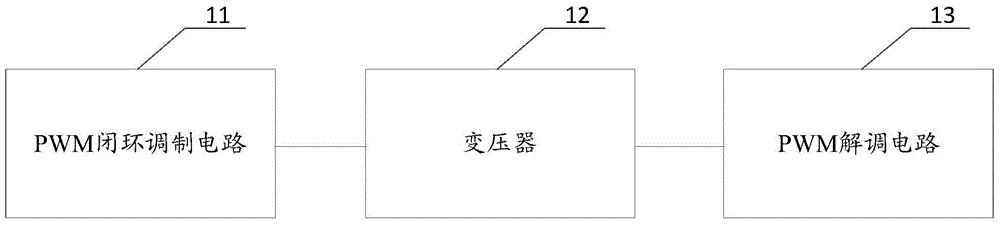
[0032] Please refer to figure 1 , figure 1 A structural schematic diagram of a power isolation sensor provided by the present invention;

[0033] The electrical isolation sensor, including:

[0034] The PWM closed-loop modulation circuit 11 is used to generate a PWM modulation signal according to the DC input signal and adopt closed-loop control;

[0035] The transformer 12 is used to couple the pulse width information in the PWM modulation signal to the PWM demodulation circuit 13;

[0036] The PWM demodulation circuit 13 is used to demodulate the pulse width information to obtain and output a DC output signal.

[0037] A power isolation sensor provided by the present invention includes a PWM closed-loop modulation circuit, a transformer, and a PWM demodulation circuit. The PWM closed-loop modulation circuit generates a PWM modulation signal based on a DC input signal and adopts closed-loop control; the transformer converts the pulse width in the PWM modulation signal to ...

Embodiment 2

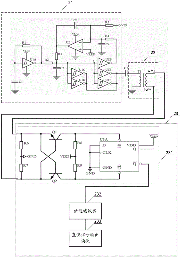
[0039] Please refer to figure 2 ,in, figure 2 A circuit diagram of another electrical isolation sensor provided by the present invention.

[0040] The galvanically isolated sensor consists of:

[0041] PWM closed-loop modulation circuit 21, transformer and PWM demodulation circuit 23;

[0042] Preferably, the PWM closed-loop modulation circuit 21 includes a square wave oscillator circuit, a first filter circuit, a second inverter U1B, a second filter circuit, an integral operational amplifier, R3, R5, C5 and a reference voltage setting device, wherein :

[0043] The square wave oscillating circuit is connected to the input terminal of the first filter circuit, the output terminal of the first filter circuit is connected to the input terminal of the second inverter U1B, and the output terminal of the second inverter U1B is respectively connected to the input terminal of the second filter circuit Terminal and connected to the input terminal of the transformer through C5, the...


PUM


Abstract

The invention discloses an electric quantity isolation sensor which comprises a pulse width modulation (PWM) closed-loop modulation circuit, a transformer and a PWM demodulation circuit, wherein the PWM closed-loop modulation circuit is used for generating a PWM modulation signal by using closed-loop control according to a direct current input signal; the transformer is used for coupling pulse information in the PWM modulation signal to the PWM demodulation circuit; and the PWM demodulation circuit is used for demodulating the pulse information to obtain and output a direct current output signal. The electric quantity isolation sensor provided by the invention adopts a closed-loop PWM modulation mode, linear pulse width modulation of the direct current input signal to the PWM modulation signal is achieved, the high isolation of the electric quantity isolation sensor is achieved, and the accuracy and the reliability of the electric quantity isolation sensor are improved.

Description

technical field [0001] The invention relates to the technical field of electrical isolation sensors, in particular to an electrical isolation sensor. Background technique [0002] With the development of new energy technologies, in order to optimize energy supply efficiency, some high-power systems adopt higher operating voltages. For example, the locomotive traction system of high-speed rail and urban rail, my country currently uses DC 750V and 1500V as the mainstream, and the highest traction voltage abroad is as high as 3600V; in addition, high-power frequency conversion or inverter controllers, aerospace DC high-voltage power distribution systems, scientific research High-voltage coils with strong magnetic fields, etc., may all work in high-voltage drive mode. For the monitoring of this type of system, on the one hand, according to the safety requirements, the working voltage is high. In order to ensure the safety of people and equipment, the isolation voltage must also ...

Claims


Application Information

Patent Timeline
Patent Type & Authority Applications(China)
IPC IPC(8): H02M3/335G01R15/14
Inventor 刘万山张宇光
Owner MIANYANG WEIBO ELECTRONICS
Why Eureka
Try Eureka