Air floating component based on porous material and platform

A technology of porous materials and air flotation platforms, which is applied in the direction of engine components, machines/supports, engine lubrication, etc., can solve the problems of unsuitable quiet and stable pressure working environment, high noise of air flotation platforms, and fluctuations in carrying capacity and other problems, to achieve good processing technology and assembly technology, to ensure quietness, and to increase the bearing capacity

Inactive Publication Date: 2015-12-02
SHANGHAI SATELLITE ENG INST
View PDF7 Cites 12 Cited by
  • Summary
  • Abstract
  • Description
  • Claims
  • Application Information

AI Technical Summary

Problems solved by technology

[0002] With the development of gas lubrication technology, the air flotation platform is widely used in occasions and tests that need to offset gravity due to its low friction, high cleanliness, long life, and high motion accuracy. However, the air flotation platform has noise during use. The shortcomings of large size and low load capacity limit its use in occasions that require a quiet working environment and high load capacity
[0003] Traditional air-floating platforms generally adopt technologies such as small hole throttling, annular throttling or slit throttling. They are characterized by simple processing technology, but when the air supply pressure changes, it is easy to produce whistling phenomenon and the sound is sharp. , and the carrying capacity also fluctuates, it is not suitable for use in quiet and stable pressure working environments

Method used


Image

  • Air floating component based on porous material and platform
  • Air floating component based on porous material and platform
  • Air floating component based on porous material and platform

Examples


Embodiment Construction

[0043] The present invention will be described in detail below in conjunction with specific embodiments. The following examples will help those skilled in the art to further understand the present invention, but do not limit the present invention in any form. It should be noted that those skilled in the art can make several modifications and improvements without departing from the concept of the present invention. These all belong to the protection scope of the present invention.

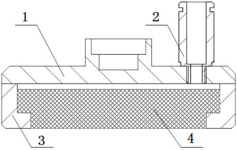
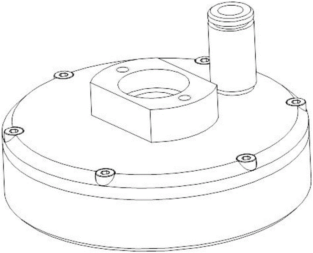
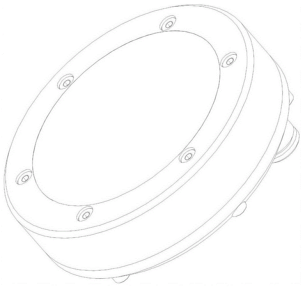
[0044] In this embodiment, the porous material-based air flotation component provided by the present invention includes an air chamber upper cover 1, a pipeline interface 2, an air chamber shell 3 and a porous module 4;

[0045] Wherein, the upper cover of the air chamber 1 is connected to the upper end of the air chamber shell 3; the porous module 4 is arranged on the inner side of the air chamber shell 3; The inner wall surface forms an air cavity between the porous module 4 and the air chamber ...


PUM


Abstract

The invention provides an air floating component based on a porous material and a platform. The air floating component comprises an air chamber upper cover, a pipeline joint, an air chamber shell and a porous module, wherein the air chamber upper cover is connected to the upper end of the air chamber shell; the porous module is arranged at the inner side of the air chamber shell; the porous module is connected to the inner wall surface of the air chamber shell to form an air cavity between the porous module and the air chamber upper cover; the pipeline joint is communicated with the air cavity through the air chamber upper cover; and the porous module is provided with multiple guide holes communicated with the upper surface and the lower surface of the porous module. A porous material is adopted to manufacture a throttle part, serving as the air flowing component, of the porous module, so that the noise under high-pressure and high-speed airflows can be eliminated, the silence of working environment is guaranteed, and the bearing capacity of the air floating component and the air floating stability are enhanced.

Description

technical field [0001] The invention relates to an air flotation component, in particular to an air flotation component and a platform based on porous materials. Background technique [0002] With the development of gas lubrication technology, the air flotation platform is widely used in occasions and tests that need to offset gravity due to its low friction, high cleanliness, long life, and high motion accuracy. However, the air flotation platform has noise during use. The shortcomings of large size and low load limit its use in occasions that require a quiet working environment and high load. [0003] Traditional air-floating platforms generally adopt technologies such as small hole throttling, annular throttling or slit throttling. They are characterized by simple processing technology, but when the air supply pressure changes, it is easy to produce whistling phenomenon and the sound is sharp. , and the carrying capacity also fluctuates, it is not suitable for use in a q...

Claims


Application Information

Patent Timeline
Patent Type & Authority Applications(China)
IPC IPC(8): F16M11/20F16N15/00
Inventor 赵枝凯满孝颖申军烽聂斌斌
Owner SHANGHAI SATELLITE ENG INST
Why Eureka
Try Eureka