Eureka AIR delivers breakthrough ideas for toughest innovation challenges, trusted by R&D personnel around the world.

Biomass high-temperature gasifying combustion furnace

A biomass and combustion furnace technology, applied in the field of combustion furnaces, can solve problems such as pyrolysis, environmental pollution, and waste of energy

Active Publication Date: 2015-12-02
WEIFANG JINSIDA NEW ENERGY SCI & TECH
View PDF8 Cites 8 Cited by
  • Summary
  • Abstract
  • Description
  • Claims
  • Application Information

AI Technical Summary

Problems solved by technology

Because the air is supplied from the combustion ash layer, the highest combustion temperature is in the oxidation combustion layer, which may easily cause the dry reduction layer to crack and produce macromolecular functional groups, and the temperature of the combustion space above the dry reduction layer cannot meet the complete combustion conditions of volatiles, thus forming thick smoke , resulting in incomplete combustion and loss of 70% of the calorific value of solid combustibles, which greatly wastes energy and pollutes the environment
Especially in the process of waste incineration, the dioxins produced by combustion cannot be decomposed without a high-temperature environment, so that the waste incineration technology cannot be promoted

Method used


Image

  • Biomass high-temperature gasifying combustion furnace
  • Biomass high-temperature gasifying combustion furnace
  • Biomass high-temperature gasifying combustion furnace

Examples


Embodiment Construction

[0027] Below in conjunction with accompanying drawing and embodiment, further elaborate the present invention. In the following detailed description, certain exemplary embodiments of the invention are described by way of illustration only. Needless to say, those skilled in the art would realize that the described embodiments can be modified in various different ways, all without departing from the spirit and scope of the present invention. Accordingly, the drawings and description are illustrative in nature and not intended to limit the scope of the claims.

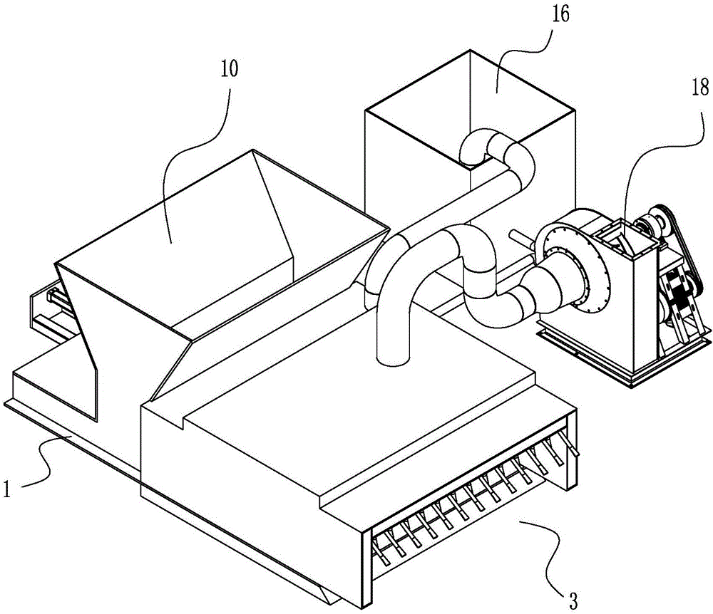
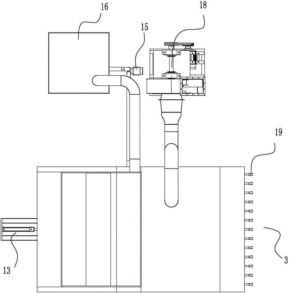
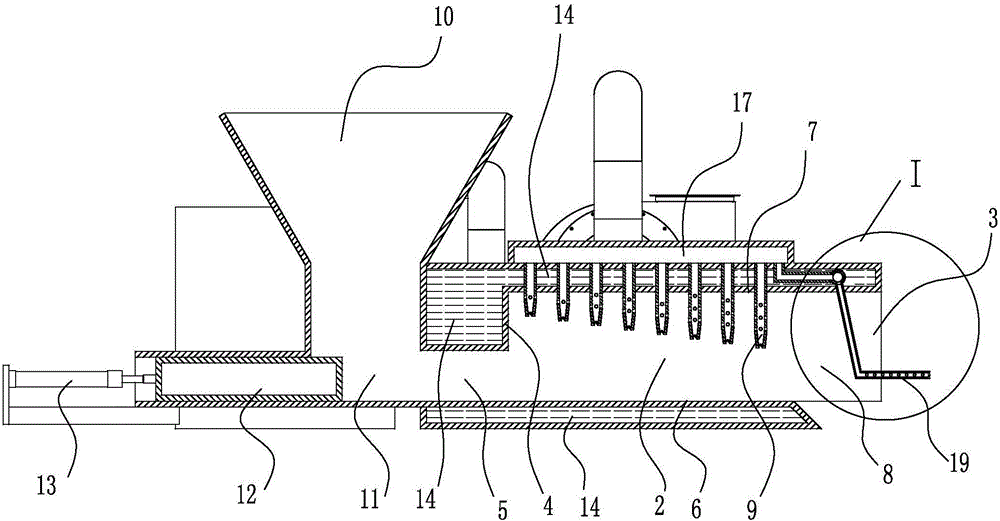
[0028] Such as figure 1 , figure 2 with image 3 As shown, the biomass high-temperature gasification combustion furnace includes a furnace body 1, and a high-temperature gasification combustion chamber 2 is arranged inside the furnace body 1. The high-temperature gasification combustion chamber 2 in this embodiment is arranged horizontally, and the high-temperature gasification The front end of the combustion chamber...


PUM


Abstract

The invention discloses a biomass high-temperature gasifying combustion furnace. The biomass high-temperature gasifying combustion furnace comprises a furnace body. A high-temperature gasifying combustion cavity is arranged in the furnace body. A plurality of air spraying pipes spraying towards the surfaces of combustion materials are arranged on a cavity top plate of the high-temperature gasifying combustion cavity. According to the biomass high-temperature gasifying combustion furnace, a traditional fire bar and fire grate structure is eliminated, a sealed cavity bottom plate is used as a material supporting plate for material combustion, and the materials on the cavity bottom plate start to be combusted from the surface layer; air is forcibly supplied to the surfaces of the materials through the air spraying pipes, oxygen-enriched combustion of a combustion layer is achieved, a large amount of heat is generated and blown towards the materials on the inner layer, the materials on the inner layer is subjected to thermal decomposition, and combustible gas is generated; the combustible gas is driven by wind of the air spraying pipes to move towards the cavity bottom plate and passes through the combustion layer on the material surface layer again through the rebound of the cavity bottom plate, the combustion layer is combusted rapidly under sufficient oxygen supply of the air spraying pipes, and the temperature of the highest combustion point can reach 1100-1300 DEG C, and harmful gas such as dioxin is decomposed completely at the high temperature; the biomass high-temperature gasifying combustion furnace has extremely great economic benefits and social benefits.

Description

technical field [0001] The invention relates to the technical field of energy utilization, in particular to a combustion furnace. Background technique [0002] The combustion principle of solid combustibles is divided into three stages: the first is the stage before ignition, including burning and drying, precipitation of volatile matter, and formation of solid charcoal. Solid combustibles are heated, dried, and evaporated in the furnace. As the temperature increases, The organic matter in coal begins to thermally decompose, mainly the volatile matter formed by the side chains and functional groups broken from the macromolecules. The main components are CO, CO2, H2, H2O, CH4 and various hydrocarbon compounds. The remaining products of pyrolysis It is solid charcoal, and solid combustibles will absorb heat during this process; the second is the combustion of volatile matter and charcoal, when the temperature reaches the ignition point, it will start to ignite, and then combus...

Claims


Application Information

Patent Timeline
Patent Type & Authority Applications(China)
IPC IPC(8): F23B40/00F23K3/00F23L1/00
CPCY02E20/34
Inventor 刘国田张大鹏范北平
Owner WEIFANG JINSIDA NEW ENERGY SCI & TECH
Why Eureka
Eureka Blog
Learn More