Narrow-gap laser-scanning multi-layer self-melting welding method based on prefabricated welding materials

A technology of laser scanning and welding methods, which is applied in the direction of laser welding equipment, welding equipment, welding/welding/cutting items, etc., can solve the problems of difficult wire filling, unstable droplet transition, etc., and achieve stable and easy welding process, reducing Pore ​​defects, the effect of reducing welding deformation

Inactive Publication Date: 2015-12-16
HARBIN INST OF TECH
View PDF8 Cites 35 Cited by
  • Summary
  • Abstract
  • Description
  • Claims
  • Application Information

AI Technical Summary

Problems solved by technology

[0005] The present invention aims to solve the problems of difficult wire filling and unstable droplet transition in the welding process of thick plates, and provides a narrow-gap laser scanning multi-layer self-fluxing welding method based on prefabricated welding materials

Method used


Image

  • Narrow-gap laser-scanning multi-layer self-melting welding method based on prefabricated welding materials
  • Narrow-gap laser-scanning multi-layer self-melting welding method based on prefabricated welding materials
  • Narrow-gap laser-scanning multi-layer self-melting welding method based on prefabricated welding materials

Examples


specific Embodiment approach 1

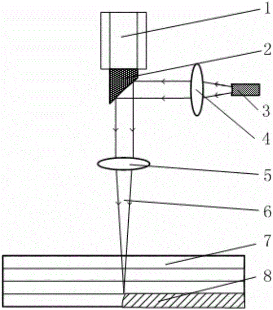
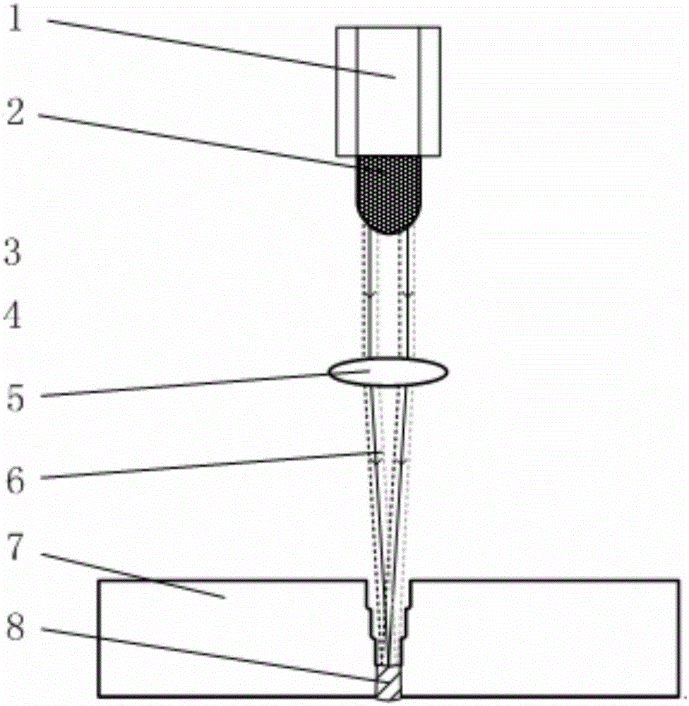
[0030] Specific implementation mode 1: The narrow gap laser scanning multilayer self-fusion welding method based on prefabricated welding material of this embodiment is carried out in the following steps:

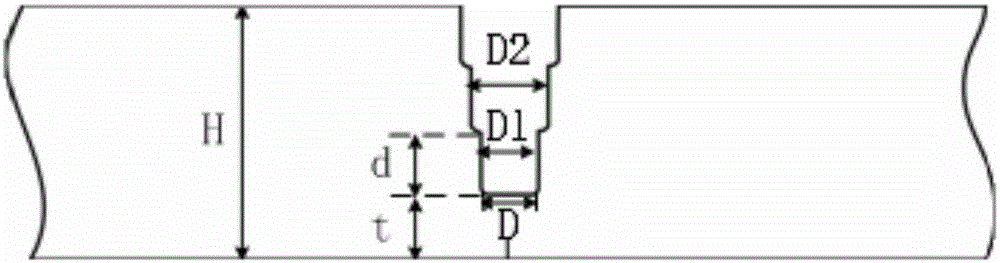
[0031] 1. Processing grooves: U-shaped grooves or V-shaped grooves with blunt edges are processed between two thick plates to be welded, the thickness of the blunt edges is t, and the U-shaped grooves or V-shaped grooves have multiple layers. For the prefabricated filling layer, the height d of the single prefabricated filling layer is controlled to be equal to the thickness t of the blunt edge. The width D of the U-shaped groove is distributed in steps, and D increases as the number of prefabricated filling layers increases, layer by layer Increase of groove width D between ΔD=D 2 -D 1 , Where D 1 Is the initial groove width, D 2 Is the second groove width, control ΔD to 0.5mm~2mm, control the initial groove width D 1 2mm~4mm; The width D of the V-shaped groove increases linea...

specific Embodiment approach 2

[0041] Embodiment 2: The difference between this embodiment and Embodiment 1 is that the thickness t of the blunt edge described in step 1 is less than or equal to the maximum penetration depth of the laser beam single-layer scanning. The other steps and parameters are the same as in the first embodiment.

[0042] The thickness t of the blunt edge depends on the maximum output power of the laser used and the beam scanning speed.

specific Embodiment approach 3

[0043] Specific embodiment three: This embodiment is different from specific embodiment one or two in that the thickness t of the blunt edge described in step one is 3 mm to 8 mm. The other steps and parameters are the same as in the first or second embodiment.


PUM

PropertyMeasurementUnit
thicknessaaaaaaaaaa

Abstract

The invention belongs to the technical field of laser processing, and particularly relates to a narrow-gap laser-scanning multi-layer self-melting welding method based on prefabricated welding materials. The method aims at solving the problems that in the thick plate welding process, wire filling is difficult, and molten drop transition is not stable. According to the narrow-gap laser-scanning multi-layer self-melting welding method based on a prefabricated filling layer, a laser scanning welding technology and narrow-gap multi-layer filled welding are skillfully combined, therefore, a laser wire filling multi-layer welding mode for thick plate structure parts is converted into a laser self-melting multi-layer welding mode, and the single-layer filling height of a weld joint in a narrow-gap groove can be precisely controlled; due to the fact that the prefabricated filling layer can prevent the weld joint from shrinking, welding deformation can be further reduced, the thick plate welding process is greatly simplified, and the welding efficiency and the welding quality are improved. The method is suitable for narrow-gap laser welding of thin plates or thick plates of different thicknesses.

Description

Technical field [0001] The invention belongs to the technical field of laser processing, and specifically relates to a narrow gap laser scanning welding method based on prefabricated welding materials. Background technique [0002] With the development of nuclear power, shipbuilding, aerospace, construction, petrochemical and other industries, various welded structures are constantly developing towards functionality and large-scale development, especially large-size medium-thick plate welded structural parts are more and more widely used. The stress and strain of the welded structure and the comprehensive performance of the joint put forward higher requirements, and new welding technical measures are needed to ensure the quality of the weld. [0003] Narrow gap welding technology is an advanced and efficient welding technology suitable for welding large and thick plates. At present, the narrow gap welding technology used in industry is mainly narrow gap arc welding technology, inc...

Claims


Application Information

Patent Timeline
Patent Type & Authority Applications(China)
IPC IPC(8): B23K26/26B23K33/00B23K101/18
CPCB23K26/26B23K33/004B23K2101/185
Inventor 陶汪蒋振国陈彦宾刘红兵李昊玉昆
Owner HARBIN INST OF TECH
Why Eureka
Try Eureka