
Flash pyrolysis reaction device

A pyrolysis reaction, fast technology, applied in the chemical industry, to achieve the effect of simplifying the process flow, rapid drying pyrolysis, and improving the efficiency of rapid pyrolysis

Active Publication Date: 2015-12-16
SHENWU TECH GRP CO LTD
View PDF7 Cites 14 Cited by
  • Summary
  • Abstract
  • Description
  • Claims
  • Application Information

AI Technical Summary

Problems solved by technology

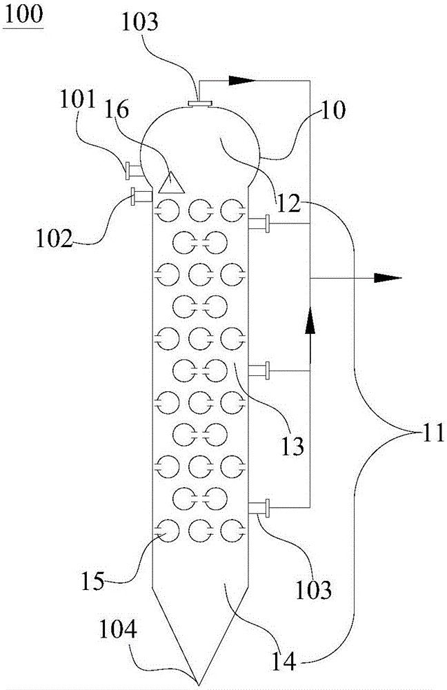
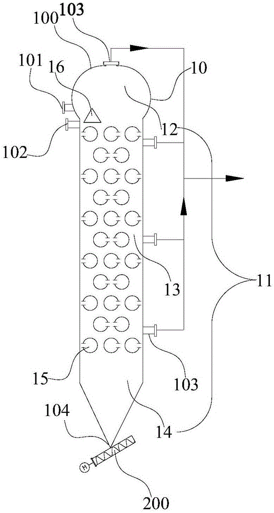
For this reason, an object of the present invention is to propose a kind of rapid pyrolysis reaction device, and the rapid pyrolysis reaction device of the present invention adopts the regenerative radiant tube as the heating source and has a complete control over the input of raw materials, the arrangement of radiant tubes, and the discharge of pyrolysis products. Reasonable design, using radiant tubes for indirect heat transfer, there is no heat carrier in the pyrolysis reaction device, and no heat carrier heating, separation and reaction processes are required, so the system process flow is simple and the operation reliability is high; The radiant tubes are arranged in multiple layers, and the outlets of pyrolysis gas are set up to realize the material uniformly entering the heating zone, and realize rapid heat transfer in the heating zone, and the pyrolysis gas is quickly collected to overcome the heat transfer effect of indirect heating. The problem of poor and small device scale, to achieve rapid pyrolysis of carbon-containing organic matter

Method used


Image

  • Flash pyrolysis reaction device
  • Flash pyrolysis reaction device
  • Flash pyrolysis reaction device

Examples


Embodiment 1

[0089] This embodiment 1 utilizes Figure 1-2 fast pyrolysis reaction device. The particle size of the raw material lignite to be pyrolyzed is less than 1mm, and the moisture content is 15.2wt%. The analysis data of the lignite is shown in Table 1.

[0090] Table 1: Lignite Analytical Data

[0091]

[0092]

[0093] The main dimensions of the fast pyrolysis reaction device are as follows: the regenerative radiant tube adopts a circular tube with a diameter of 300mm, the distance between the outer walls of each layer of adjacent radiant tubes in the horizontal direction is 200mm, and the distance between the outer walls of the adjacent radiant tubes in the upper and lower layers is 300mm , the number of layers of regenerative radiant tubes is 15 layers, and the temperature of the regenerative radiant tubes in the pyrolysis zone and the temperature of each area of ​​the reactor formed are shown in Table 2. The average residence time of materials in the reactor is 2.9s , ...

Embodiment 2

[0097] This example uses Figure 1-2 fast pyrolysis reaction device. The lignite raw material to be pyrolyzed is the same as in Example 1.

[0098] The main dimensions of the fast pyrolysis reaction device are as follows: the regenerative radiant tube adopts a circular tube with a diameter of 100mm, the outer wall distance between adjacent radiant tubes in each layer is 100mm horizontally, and the outer wall distance between adjacent radiant tubes in the upper and lower layers is 200mm , the number of layers of regenerative radiant tubes is 30 layers, the particle size of lignite treated is below 1mm, and the moisture content is 15.2wt%. As shown in 3, the average residence time of the material in the reactor is 30s, wherein, the pyrolysis gas is discharged and then cooled by conventional cyclone dedusting to obtain a tar yield of 13.2wt%, a dust content of 2.4wt%, and a combustible gas yield of 16.7 wt%, semi-coke yield is 51.4wt%, which is 61.0wt% higher than the tar yield...

Embodiment 3

[0103] This example uses Figure 1-2 fast pyrolysis reaction device. The lignite raw material to be pyrolyzed is the same as in Example 1.

[0104] The main dimensions of the fast pyrolysis reaction device are as follows: the regenerative radiant tube adopts a circular tube with a diameter of 500mm, the outer wall distance between adjacent radiant tubes on each layer is 500mm horizontally, and the outer wall distance between adjacent radiant tubes on the upper and lower layers is 450mm , the number of layers of the regenerative radiant tube is 10 layers, the lignite particle size of the process is below 1mm, and the moisture is 15.2%. The temperature of the regenerative radiant tube in the pyrolysis zone and the temperature in each zone of the reactor formed are consistent with the embodiment 1 is the same, the average residence time of the material in the reactor is 15.6s, wherein, the pyrolysis gas is discharged through the conventional cyclone dedusting and then cooled to ...


PUM

PropertyMeasurementUnit
heightaaaaaaaaaa
diameteraaaaaaaaaa
particle diameteraaaaaaaaaa

Abstract

The invention discloses a flash pyrolysis reaction device. The flash pyrolysis reaction device comprises a reactor, multiple layers of heat storage type radiant tubes, a distributor, a material inlet, a distribution gas inlet, multiple pyrolysis gas outlets and a semicoke outlet. The reactor comprises a reactor body, and a reaction space is defined in the reactor body and forms a dispersion zone, a pyrolysis zone and a discharge zone from top to bottom. The multiple layers of heat storage type radiant tubes are distributed at intervals in the pyrolysis zone in the height direction of the reactor body, and each layer of heat storage type radiant tubes comprises multiple heat storage type radiant tubes distributed at intervals in the horizontal direction. The material inlet is located in the position, above the distributor, in the dispersion area. The distribution gas inlet is located in the dispersion zone and communicated with the distributor so that materials in the distributor can be conveniently blown out through distribution gas to enter the dispersion zone and then evenly fall into the pyrolysis zone. The multiple pyrolysis gas outlets are formed in the dispersion zone and / or the pyrolysis zone. The semicoke outlet is formed in the discharge zone. The device can significantly increase the tar yield and greatly simplify the flash pyrolysis reaction technological process.

Description

technical field [0001] The invention belongs to the field of chemical industry, in particular, the invention relates to a fast pyrolysis reaction device. Background technique [0002] Rapid pyrolysis can cause carbon-containing polymers to rapidly undergo bond-breaking reactions, inhibit the secondary pyrolysis reaction and cross-linking reaction of pyrolysis products, reduce the gas and semi-coke products in the pyrolysis process, and increase the tar yield. From the perspective of economic and social benefits, fast pyrolysis technology is a very suitable treatment technology for carbonaceous substances. [0003] Fast pyrolysis reactors are generally developed as fluidized bed, moving bed, rotating bed and other reactors, and use gas or solid heat carrier to meet the temperature field and temperature rise rate requirements, but the fast pyrolysis reactor using heat carrier involves heat carrier The uniform distribution, mixing and reaction of the raw materials, as well as ...

Claims


Application Information

Patent Timeline
Patent Type & Authority Applications(China)
IPC IPC(8): C10B53/04C10B47/00C10B27/00
Inventor 吴道洪陈水渺肖磊
Owner SHENWU TECH GRP CO LTD
Learn More