Contraposition double-eccentric-wheel sliding groove push-pull reciprocating compressed air pressurizing homogeneity compression ignition internal combustion engine

A technology of double eccentric wheel and sliding groove, applied in the direction of machine/engine, mechanical equipment, etc.

Inactive Publication Date: 2015-12-16
高阳
View PDF0 Cites 1 Cited by
  • Summary
  • Abstract
  • Description
  • Claims
  • Application Information

AI Technical Summary

Problems solved by technology

[0007] The first technical problem solved by the present invention is: change the self-inhalation mode of the internal combustion engine into a scavenging pump pressurized forced air intake, and change the traditional crank-link mechanism-driven scavenging pump to be coaxial with the power output shaft of the internal combustion engine. The air compressor driven by the sliding chute mechanism of the opposite double eccentric whe

Method used


Image

  • Contraposition double-eccentric-wheel sliding groove push-pull reciprocating compressed air pressurizing homogeneity compression ignition internal combustion engine
  • Contraposition double-eccentric-wheel sliding groove push-pull reciprocating compressed air pressurizing homogeneity compression ignition internal combustion engine
  • Contraposition double-eccentric-wheel sliding groove push-pull reciprocating compressed air pressurizing homogeneity compression ignition internal combustion engine

Examples


Embodiment Construction

[0021] In order to clarify the purpose of the present invention more clearly, the technical innovation advantages and beneficial effects of generations of the present invention are presented, so as to make the content of the present invention more concise and easy to understand. Below in conjunction with the technical scheme of the specific embodiment of the present invention, further describe in detail:

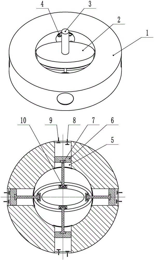
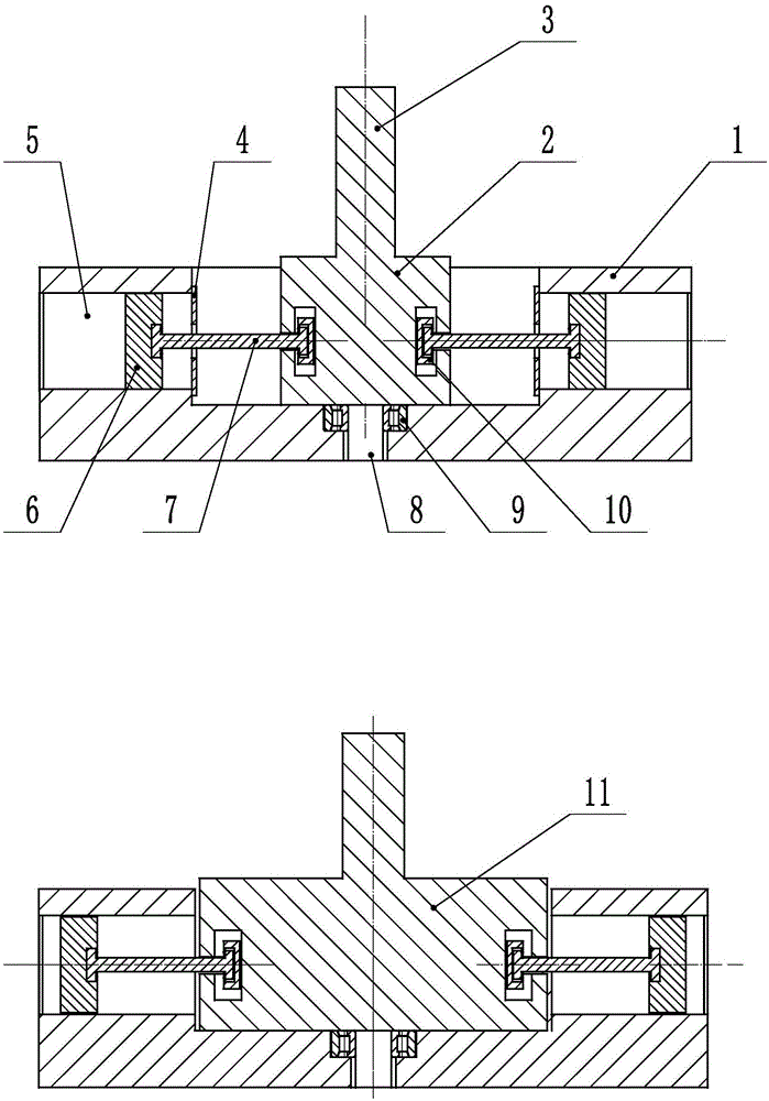
[0022] Such as figure 1 As shown in the schematic diagram of the embodiment, it is an air compressor driven by opposing double eccentric sliding grooves or a scavenging pump for an internal combustion engine. cover (such as figure 1 1, 2, 3, 4), the air pump cylinder, piston, connecting rod, exhaust valve, intake valve and connecting rod sliding bearings drive the piston to reciprocate in the sliding groove of the double eccentric wheel in a sliding push-pull manner (Such as figure 1 5, 6, 7, 8, 9, 10) in the logo are combined.

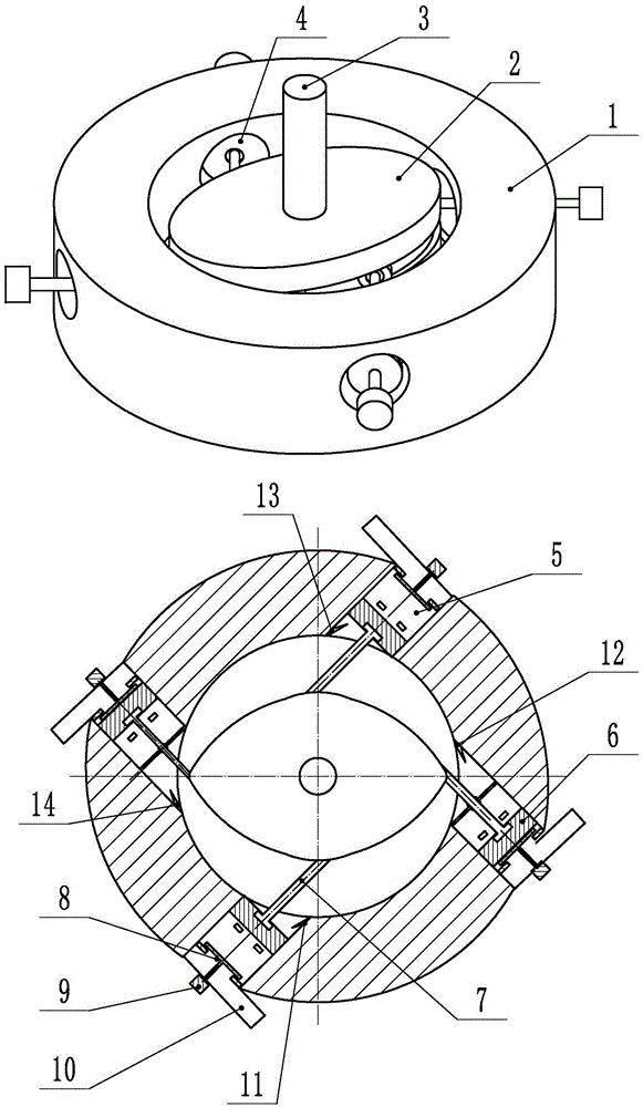
[0023] Such as figure 2 As shown in the...


PUM


Abstract

The invention provides a contraposition double-eccentric-wheel sliding groove push-pull reciprocating compressed air pressurizing homogeneity compression ignition internal combustion engine. The eccentric distance of a rotating double-eccentric-wheel serves as a reciprocating stroke to drive pistons to complete air suction, compression, acting pressure gas discharging, pressurized air is supplied to a coaxial double-eccentric-wheel sliding groove type power output internal combustion engine, and the pressurized air flows quickly into all air cylinders of the internal combustion engine through an air intake branch; the air flowing into the air cylinder is the pressurized air 2-5 times larger than the atmospheric pressure, the air exchange efficiency, air inlet density, air inflation and effective internal combustion engine pressure are greatly improved, and the internal combustion engine is a real pressurizing homogeneity compression ignition two-stroke internal combustion engine; even numbers of air cylinders are correspondingly arranged in pairs and evenly embedded into the periphery of the same circular-ring-shaped cylinder body; the inner circle center is the rotating double-eccentric-wheel sliding groove provided with an integrated power shaft and precisely assembled to and connected with a T-shaped sliding mechanism at a big end of connection rod in a sliding mode to transfer power, the rotating double-eccentric-wheel sliding groove provided with the integrated power shaft rotates by a circle, the big end of the connection rod slides in a limiting sliding groove with the eccentric distance as the stroke, and all the air cylinder pistons are pushed and pulled by two reciprocating strokes, in other words, the pistons act twice when the power shaft rotates by a circle.

Description

technical field [0001] The push-pull reciprocating air compression supercharged homogeneous compression ignition internal combustion engine with opposite double eccentric sliding grooves converts mechanical energy into air combustion-supporting fuel heat energy and then into power mechanical energy. The invention belongs to the technical field of internal combustion engine and the stepless variable hydraulic pump converts mechanical energy into high-pressure fluid energy, and the stepless variable hydraulic motor converts high-pressure fluid fluid energy into mechanical energy. The invention belongs to the technical field of mutual conversion of mechanical energy and high-pressure fluid energy. technical background [0002] The internal combustion engine was born in 1860. During the 155 years of development, it has contributed a lot to the development of human society and economy. Thanks to the hard work of several generations of experts, scholars and many internal combusti...

Claims


Application Information

Patent Timeline
IPC IPC(8): F02B61/06
Inventor 高士炳高阳
Owner 高阳
Why Eureka
Try Eureka