Combination switch for looped-network switch cabinet

A technology of ring network switch cabinet and compound switch, which is applied in the manufacture of protective switch parts, protective switches, emergency protection devices, etc. Short circuit and leakage, ensure the effect of safe use

Inactive Publication Date: 2015-12-16
扬中市佳旺华电器有限公司
View PDF9 Cites 6 Cited by
  • Summary
  • Abstract
  • Description
  • Claims
  • Application Information

AI Technical Summary

Problems solved by technology

This leads to complicated external wiring of the composite switch, interlaced external connecting wires, large installation space required, error-prone installation and wiring process, cumbersome installation process, and potential safety hazards in exposed connecting wires

Method used


Image

  • Combination switch for looped-network switch cabinet
  • Combination switch for looped-network switch cabinet

Examples


Embodiment 1

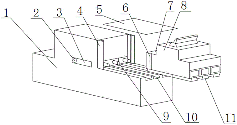
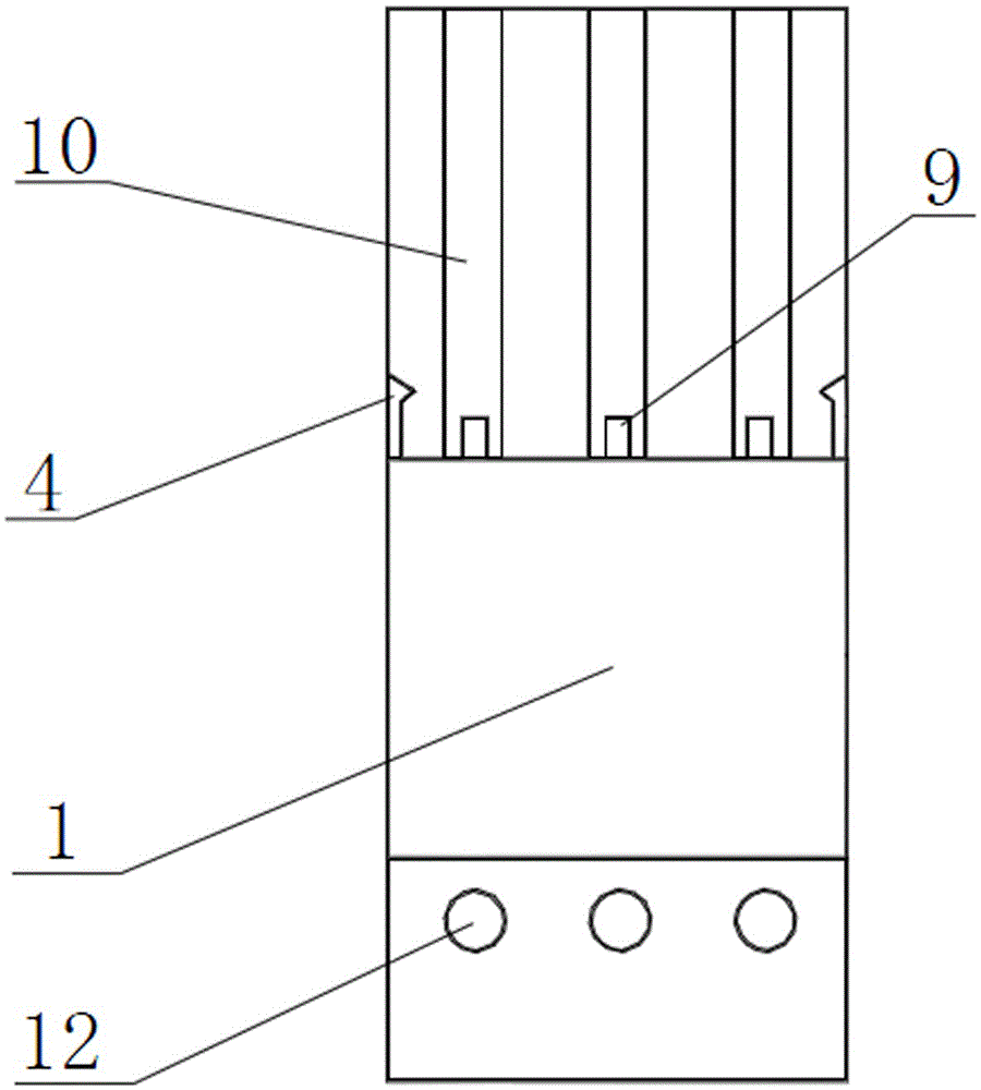
[0040] The compound switch that is used for the ring network switchgear of this embodiment is as figure 1 with 2 As shown, it includes a circuit breaker 8, a housing 1 and a circuit structure arranged in the housing 1, and also includes an operating rod 2. The housing 1 is provided with a chute 10, and the circuit breaker 8 is provided with a The slide block 11, the circuit breaker 8 is connected with the chute slide 10 through the slide block 11, and the chute 10 and the slide block 11 are three matched pairs;

[0041] The circuit structure is provided with a plug-in terminal 9 outside the housing 1. The plug-in terminal 9 is embedded in the housing 1 and can reciprocate along its own axial direction. The circuit breaker 8 is embedded with a circuit breaker 8 that can be connected with the The socket end 9 is socketed with the conductive socket end, and the socket end 9 and the socket end are three matched pairs. There is an opening 3 on the side wall of the housing 1 close t...

Embodiment 2

[0058] The composite switch for the ring main switchgear of this embodiment is basically the same as that of Embodiment 1, except that the mass percentages of the components in the sealing plate are: cross-linked polyethylene 0.24%, styrene 2.47%, butyl peroxide acetate 0.73% ester, 0.78% butyl peroxybenzoate, 0.27% magnesium stearate, 1.23% iron fulvic acid, 3.48% calcium oxide, 2.47% magnesium oxide, 3.47% glass fiber, 0.38% acetylacetone, polyamide resin 0.56%, epoxy resin 0.21%, 3-aminopropyltriethoxysilane 0.17%, vinyltrimethoxysilane 0.35%, hydroxyl silicone oil 0.13%, kapok fiber 24.65%, polyester fiber 16.52%, the balance is Polyester fiber.


PUM


Abstract

The invention discloses a combination switch for a looped-network switch cabinet. The combination switch comprises a circuit breaker, a shell, an operation rod and a circuit structure, wherein the circuit structure is arranged in the shell, the shell is provided with a sliding groove, the circuit breaker is provided with a sliding block adaptive to the sliding groove, the circuit structure is provided with a plug-in end outside the shell, the plug-in end can do axial reciprocating movement to be embedded onto the shell along the plug-in end, a sheath end is embedded into the circuit breaker and can be sheathed in and conducted with the plug-in end during the sliding process of the circuit breaker, an opening is formed on the side wall of the shell, the operation rod penetrates through the opening and is fixedly connected with the plug-in end, a groove is arranged at a position where the circuit breaker props against the shell, a sealing plate covers the upper part of the groove, and a vacuum gap is formed between the sealing plate and the groove. The vacuum gap has an effect of heat insulation, the influence of an exterior temperature environment to a connection part of the plug-in end and the sheath end can be prevented, so that the combination switch can be applicable for various working environments with high temperature.

Description

technical field [0001] The invention relates to a composite switch for a ring network switch cabinet, belonging to the technical field of switch devices for power supply or power distribution. Background technique [0002] The switch cabinet is a kind of electrical equipment. The outside line of the switch cabinet first enters the main control switch in the cabinet, and then enters the sub-control switch. Each branch is set according to its needs. Such as instruments, automatic controls, motor magnetic switches, various AC contactors, etc., some also have high-voltage room and low-voltage room switch cabinets, high-voltage busbars, such as power plants, etc. load shedding. [0003] The main function of the switchgear is to open and close, control and protect electrical equipment during the process of power generation, transmission, distribution and power conversion in the power system. The components in the switch cabinet are mainly composed of circuit breakers, composite ...

Claims


Application Information

Patent Timeline
Patent Type & Authority Applications(China)
IPC IPC(8): H01H71/02H01H69/00
CPCH01H71/0214H01H69/00
Inventor 何春娣李德顺
Owner 扬中市佳旺华电器有限公司
Why Eureka
Try Eureka