Connecting method and connecting structure of valve reactor and voltage source transverter in flexible direct current power transmission

A flexible direct current transmission and voltage source converter technology, which is applied in the installation of cables, power distribution substations, electrical components, etc., can solve the problems of heavy operation and maintenance workload, bulky transition busbar, poor flexibility and adaptability, etc. Operation and maintenance, reducing the total length of wiring, and strong adaptability

Pending Publication Date: 2015-12-16
CHINA ENERGY ENG GRP GUANGDONG ELECTRIC POWER DESIGN INST CO LTD
View PDF3 Cites 4 Cited by
  • Summary
  • Abstract
  • Description
  • Claims
  • Application Information

AI Technical Summary

Problems solved by technology

The existing connection method has the following disadvantages: (1) In order to realize the phase sequence transformation on the side of the valve reactor, a transition busbar needs to be installed, and the project investment is high
(2) The transition bus is bulky and occupies a large area
(3) Large workload of operation and maintenance
(4) Poor flexibility and adaptability, especially for multi-layer indoor flexible DC converter stations

Method used


Image

  • Connecting method and connecting structure of valve reactor and voltage source transverter in flexible direct current power transmission
  • Connecting method and connecting structure of valve reactor and voltage source transverter in flexible direct current power transmission
  • Connecting method and connecting structure of valve reactor and voltage source transverter in flexible direct current power transmission

Examples


specific Embodiment 1

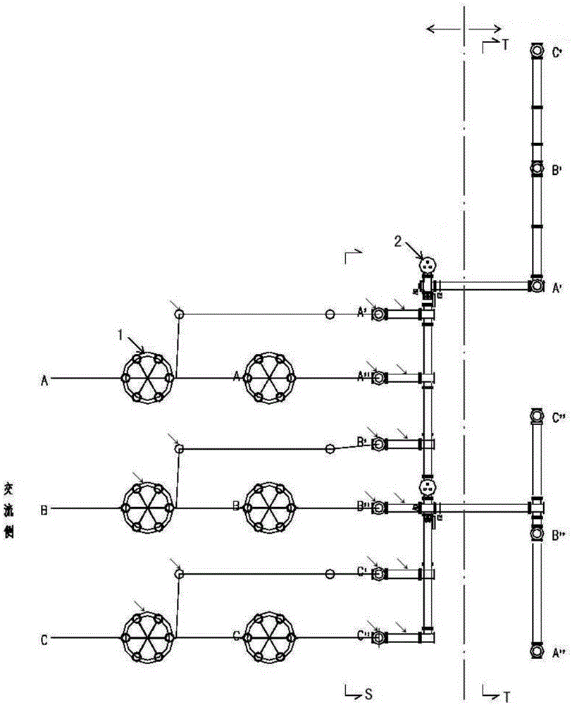
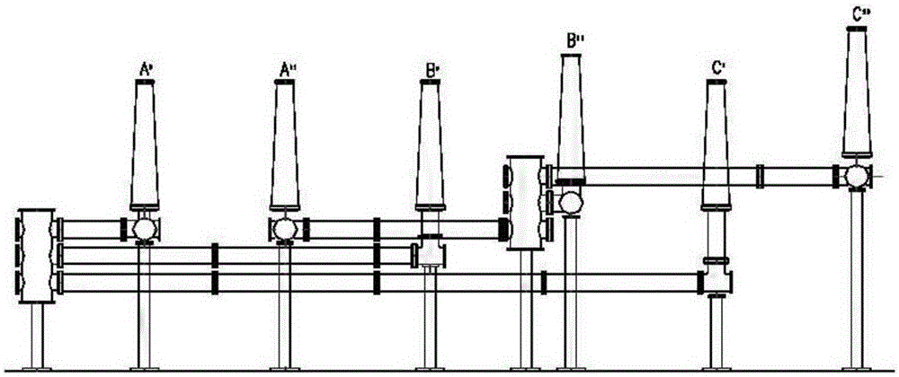
[0043] refer to Figure 1 to Figure 3 , the connection structure between the valve reactor and the voltage source converter in the flexible DC transmission involved in this embodiment includes the valve reactor on the AC side and the converter in the valve hall, and its structural features are: the valve reactance on the AC side The gas-insulated metal-enclosed transmission line structure GIL is set at the junction of the inverter and the converter in the valve hall. The gas-insulated metal-enclosed transmission line structure GIL is SF6GIL, and its segmental assembly and testing are completed in the factory. The maximum segment length is 18 m, the elbow section is pre-assembled in the factory, and its bending angle is 79° to 179°, which is used to change the line direction to reduce the total length of wiring. GIL also has pre-assembled T-shaped pipe sections, which are convenient for connecting branch circuits and other system components. Including SF6 arrester and voltage t...

specific Embodiment 2

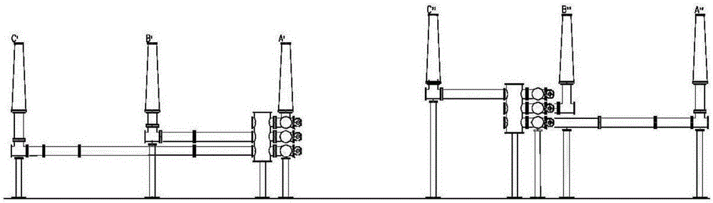
[0056] The characteristics of this embodiment are: the layout of the GIL outlet bushings is flexibly adjusted according to the layout requirements of the valve reactors and converters, and the valve reactors on the AC side are arranged in parallel double rows according to the upper and lower bridge arms. The converter station of flexible direct current transmission is designed according to indoor multi-layer layout, and the whole station is divided into 110kV AC power distribution device area, connecting transformer area, starting circuit and valve reactor area, valve hall area and DC field area according to electrical functions; , 110kV AC power distribution device area, connecting transformer area, starting circuit and valve reactor area are located on the first floor of the AC and DC power distribution device building, the valve hall and DC field are arranged on the second floor of the AC and DC power distribution device building, and the valve reactor The connection with th...

specific Embodiment 3

[0057] The feature of this embodiment is that compressed air is used to replace SF6 in the GIL to reduce costs and benefit environmental protection, and at the same time adopts a tubular structure, which is not affected by the environment. The use of this technology can effectively save the occupied area, has strong safety, is convenient for maintenance, and prevents the occurrence of vicious accidents caused by climate. The analysis shows that CAIL is a promising new environmentally friendly connection method.


PUM


Abstract

The invention relates to a connecting method and connecting structure of a valve reactor and a voltage source transverter in flexible direct current power transmission. The method is characterized by including the steps: connecting a valve reactor at an AC side with a transverter in a valve hall by means of a gas insulated metal enclosed power transmission line structure GIL, and converting the phase sequence of the valve reactor at the AC side into a phase sequence that accords with the requirement of the phase sequence of the transverter in the valve hall through pipeline changes of the gas insulated metal enclosed power transmission line structure GIL. In this way, the phase sequence of the AC side matches the phase sequence of a DC side, so a transition bus structure at the AC side is not needed. The connecting structure of valve reactor and a voltage source transverter in flexible direct current power transmission comprises a valve reactor at an AC side and a transverter in a valve hall. The structural characteristics are that a connecting place of the valve reactor at the AC side and the transverter in the valve hall is provided with a gas insulated metal enclosed power transmission line structure GIL, and the gas insulated metal enclosed power transmission line structure GIL is an SF6 GIL. The beneficial effects are that the land occupation area is reduced, construction investments are reduced, the connecting structure is flexible to arrange and is high in adaptability, etc.

Description

technical field [0001] The invention relates to a connection method and a connection structure between a valve reactor and a voltage source converter in a flexible direct current transmission, and is suitable for a flexible direct current transmission converter station. The invention belongs to the technical field of flexible direct current transmission. Background technique [0002] The flexible DC transmission technology based on the voltage source converter is the third generation of DC technology. Its first test project was put into operation in Sweden in 1997, and then it has developed rapidly. ABB named the technology "Light DC (HVDC-Light)", and Siemens named it "New DC (HVDC-Plus)". In China, it is generally named "HVDC-Flexible". [0003] The biggest difference between flexible DC and conventional DC is the use of fully controlled switching devices, voltage source converters and PWM modulation technology. It can achieve independent control of active power and rea...

Claims


Application Information

Patent Timeline
Patent Type & Authority Applications(China)
IPC IPC(8): H02B7/06H02B1/20H02G5/00
Inventor 郭金川周敏贺艳芝李扶中王宏斌孔志达冯晓东陈冰
Owner CHINA ENERGY ENG GRP GUANGDONG ELECTRIC POWER DESIGN INST CO LTD
Why Eureka
Try Eureka