Efficient energy-saving large-air-quantity low-concentration organic waste gas recovery and treatment device and method
An organic waste gas, high-efficiency and energy-saving technology, applied in separation methods, chemical instruments and methods, dispersed particle separation, etc., can solve the problems of high operating costs, high energy consumption, limited application areas, etc., to improve recovery efficiency and overcome high cost. , the effect of reducing energy consumption
- Summary
- Abstract
- Description
- Claims
- Application Information
AI Technical Summary
Problems solved by technology
Method used
Image

Examples
Embodiment Construction
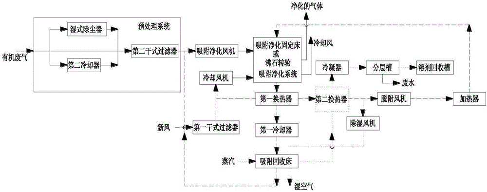
[0037] Such as figure 1 As shown, the present invention is a high-efficiency and energy-saving high-volume and low-concentration organic waste gas recovery and treatment device, including a pretreatment system and an adsorption purification device. The output end of the pretreatment system is connected to the organic waste gas inlet of the adsorption purification device through an adsorption purification fan. The recovery device also includes a first heat exchanger, a first cooler, an adsorption recovery bed, a condenser, a layered tank, a solvent recovery tank, a heater, a first dry filter, a dehumidification fan and a cooling fan;
[0038] The adsorption and purification device is also provided with a purified gas outlet, a desorption gas inlet, a concentrated airflow outlet, a cooling air inlet, and a cooling air outlet;
[0039]The first heat exchanger is provided with a fresh air inlet, a fresh air outlet, a concentrated airflow inlet and a concentrated airflow outlet;
...
PUM
 Abstract
Description
Claims
Application Information