Supercharge Your Innovation With Domain-Expert AI Agents!

Boiler flue gas waste heat recovery system

A waste heat recovery system, boiler flue gas technology, applied in heating systems, hot water central heating systems, preheating and other directions, can solve the problems of easily polluted condensate water quality, consumption, waste of working materials, etc., to save production costs, The effect of low failure rate requirements and high reliability requirements

Active Publication Date: 2015-12-23
CHINA ENERGY ENG GRP GUANGDONG ELECTRIC POWER DESIGN INST CO LTD
View PDF8 Cites 1 Cited by
  • Summary
  • Abstract
  • Description
  • Claims
  • Application Information

AI Technical Summary

Problems solved by technology

[0003] Due to the different cooling sources of the flue gas waste heat system in the heating period and the non-heating period of the existing flue gas recovery system, the water side system of the low-temperature economizer needs to be switched according to the change of the load nature of the unit. During the switching process, due to condensation Water and heating network water share the pipeline between the inlet and outlet shut-off valves, so there is a problem of using the same pipeline with different water qualities alternately. If the switching between heating network water and condensate water is not performed properly, the condensate water quality is easily polluted, and the pre-washing Need to consume part of condensed water or demineralized water, waste of working fluid

Method used


Image

  • Boiler flue gas waste heat recovery system

Examples


Embodiment Construction

[0024] Embodiments of the present invention are described in detail below:

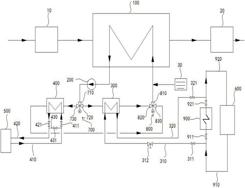
[0025] Such as figure 1 As shown, a boiler flue gas waste heat recovery system includes an economizer 100, a pump body 200, a first heat exchanger 300, a second heat exchanger 400, a heat network water system 500 and a steam turbine condensate water system 600 The economizer 100 is installed after the dust collector 10 and before the desulfurization island 20. The economizer 100, the heat exchange medium side of the first heat exchanger 300 and the pump body 200 are connected in sequence to form a first circulation loop. The economizer 100, The heat exchange medium side of the second heat exchanger 400 and the pump body 200 are sequentially connected to form a second circulation loop, the first water side of the first heat exchanger 300 is connected to the condensate water system 600 to form a first heat exchange loop, and the second heat exchanger The second water side of the heater 400 communicates...


PUM


Abstract

The invention discloses a boiler flue gas waste heat recovery system. The boiler flue gas waste heat recovery system comprises a coal economizer, a pump body, a first heat exchanger, a second heat exchanger, a heating network water system and a condensate water system. The coal economizer, the heat exchange medium side of the first heat exchanger and the pump body are communicated sequentially to form a first circulation circuit. The coal economizer, the heat exchange medium side of the second heat exchanger and the pump body are communicated sequentially to form a second circulation circuit. The first water side of the first heat exchanger is communicated with the condensate water system to form a first heat exchange circuit. The second water side of the second heat exchanger is communicated with the heating network water system to form a second heat exchange circuit. According to the boiler flue gas waste heat recovery system, the independent heat exchange of heating network water and condensate water is achieved; the water quality interference phenomenon is effectively prevented; it is ensured that the condensate water of a main machine is not polluted. Meanwhile, the indirect heat exchange mode that heat exchange is conducted between heat exchange media and boiler flue gas is adopted, so that the condensate water and the heating network water do not make contact with the coal economizer directly; the pressure resisting requirement of the coal economizer is lowered; the production cost of raw materials can be reduced.

Description

technical field [0001] The invention relates to the technical field of boiler flue gas waste heat recovery, in particular to a boiler flue gas waste heat recovery system. Background technique [0002] The most important loss in boiler operation is exhaust heat loss. Reducing exhaust loss and rational use of flue gas waste heat are particularly important for saving energy and improving the economy of power plants. Low-temperature economizers are often used in the boiler flue gas waste heat recovery process, that is, condensed water and / or hot network water are used as cold sources to absorb flue gas waste heat. When exchanging heat with condensed water during the non-heating period, the condensed water absorbs the exhaust gas heat in the low-temperature economizer, reduces the exhaust gas temperature, is heated by itself, and returns to the low-pressure heater system of the steam turbine to replace part of the low-pressure heater It is an integral part of the steam turbine t...

Claims


Application Information

Patent Timeline
IPC IPC(8): F22D1/00F24D3/02F24D3/10
Inventor 白建基张鹏
Owner CHINA ENERGY ENG GRP GUANGDONG ELECTRIC POWER DESIGN INST CO LTD
Features
  • R&D
  • Intellectual Property
  • Life Sciences
  • Materials
  • Tech Scout
  • Unparalleled Data Quality
  • Higher Quality Content
  • 60% Fewer Hallucinations
Learn More