A preparation method of porous heat transfer surface with local controllable hydrophilicity and hydrophobicity

A heat transfer surface, hydrophilic technology, applied in the field of heat transfer enhancement, can solve the problems of heat exchanger burning, heat transfer surface dry burning, heat transfer efficiency reduction, etc., to improve heat flow density, reduce superheat, and promote perfection and developmental effects

Active Publication Date: 2017-07-21
NORTH CHINA ELECTRIC POWER UNIV (BAODING)
View PDF6 Cites 1 Cited by
  • Summary
  • Abstract
  • Description
  • Claims
  • Application Information

AI Technical Summary

Problems solved by technology

Once the superheat of the wall surface exceeds the critical value, the boiling enters the film boiling stage, and the heat transfer surface appears dry burning, and the heat exchanger is in danger of burning out, and its heat transfer efficiency is significantly reduced; therefore, nucleate boiling is a boiling phase transition in practical applications. The main form of heat transfer

Method used


Image

  • A preparation method of porous heat transfer surface with local controllable hydrophilicity and hydrophobicity
  • A preparation method of porous heat transfer surface with local controllable hydrophilicity and hydrophobicity
  • A preparation method of porous heat transfer surface with local controllable hydrophilicity and hydrophobicity

Examples


Embodiment 1

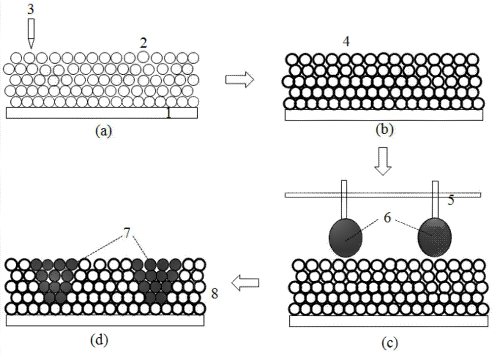
[0043] Sintered porous metal surface: choose copper metal as the heat transfer metal base surface material 30mm×40mm, firstly perform ultrasonic surface cleaning treatment; choose metal Cu / CuO micron particles with a scale of 600nm‐1μm with good heat transfer performance; use plastic scraper Spread the metal particles on the surface of the substrate with a thickness of 120 microns. Fix the heat-exchanging metal base surface in the positioning groove; under the protection of nitrogen, sinter at 600-700 ° C for 3 hours, and then cool naturally under the protection of nitrogen; obtain a porous metal heat transfer surface.

[0044] Hydrophilic treatment of porous metal heat transfer surface: First, ultrasonically clean the porous metal heat transfer surface (porous metal structure) with acetone for 20 minutes, then wash with alcohol, isopropanol, and deionized water in sequence, and use 2.0M hydrochloric acid to remove the oxide film. Wash with deionized water, dry in nitrogen; th...

Embodiment 2

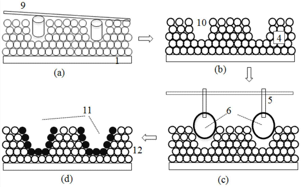
[0047] Sintered porous metal surface: choose copper metal as the heat transfer metal base surface material 30mm×40mm, firstly perform ultrasonic surface cleaning treatment; choose metal Cu / CuO micron particles with a scale of 10‐35μm with good heat transfer performance; use plastic scraper Spread the metal particles on the surface of the substrate with a thickness of 100-200 microns. Fix the heat-exchanging metal base surface in the positioning groove; under the protection of nitrogen, sinter at 600-700 ° C for 3 hours, and then cool naturally under the protection of nitrogen; obtain a porous metal heat transfer surface.

[0048] Hydrophilic treatment of porous metal heat transfer surface: First, ultrasonically clean the porous metal heat transfer surface (porous metal structure) with acetone for 20 minutes, then wash with alcohol, isopropanol, and deionized water in sequence, and use 2.0M hydrochloric acid to remove the oxide film. Wash with deionized water, dry in nitrogen; ...


PUM

PropertyMeasurementUnit
thicknessaaaaaaaaaa
thicknessaaaaaaaaaa
thicknessaaaaaaaaaa

Abstract

The invention belongs to a preparing method for a porous heat transfer surface with locally controlled hydrophilia and hydrophobicity in the technical field of enhancement of heat transfer. The preparing method mainly comprises three steps, i.e., the first step: sintering a porous metal surface; the second step: performing comprehensive hydrophilization processing on a porous structure; and the third step: designing and positioning a microcapillary liquid injector, injecting a hydrophobization processing solution into certain parts of the surface of the porous structure by using a positioning function for performing local hydrophobization processing, and finally obtaining the porous heat transfer surface with a controlled hydrophilic capillary structure and local hydrophobicity. The efficient heat transfer porous structure is used for coupling with controlled local hydrophilia and hydrophobicity modification processing, thus promoting the fast transfer of liquid in the porous heat transfer surface and accelerating supply of a liquid phase to a hydrophobic evaporation core; meanwhile, the hydrophobic evaporation core reduces the adsorption to air bubbles and promotes fast separation of the air bubbles, the controllability of the porous structure heat transfer surface is improved, and the prepared efficient and controlled porous heat transfer surface belongs to a technical innovation in the field of machining of heat exchangers.

Description

technical field [0001] The invention belongs to the technical field of enhanced heat transfer, in particular to a method for preparing a porous heat transfer surface with locally controllable hydrophilicity and hydrophobicity. Background technique [0002] As a high-efficiency heat transfer method, boiling phase change heat transfer is widely used in high-efficiency heat exchangers, rapid cooling, and energy storage. However, in view of the phenomenon of film boiling or dry wall in the boiling process, the heat transfer efficiency is significantly reduced, and even the equipment is burned. In the actual application process, the boiling heat transfer must be controlled in the nucleate boiling stage with high heat transfer coefficient and low wall temperature; or in order to avoid dry wall and burnout phenomenon, increase the requirements for equipment materials and limit the application conditions of heat exchangers. Therefore, to improve the heat transfer efficiency of boil...

Claims


Application Information

Patent Timeline
Patent Type & Authority Patents(China)
IPC IPC(8): F28F13/18B22F5/10
Inventor 陈宏霞徐进良
Owner NORTH CHINA ELECTRIC POWER UNIV (BAODING)
Why Eureka
Try Eureka