Continuous nonsingular terminal sliding mode control method based on Buck converter
A technology of non-singular terminal and control method, which is applied in the field of continuous non-singular terminal sliding mode control based on Buck converter, and can solve problems such as low voltage response speed and poor steady state
- Summary
- Abstract
- Description
- Claims
- Application Information
AI Technical Summary
Problems solved by technology
Method used
Image
Examples
specific Embodiment approach 1
[0065] Specific embodiment one: the continuous non-singular terminal sliding mode control method of the Buck converter of the present embodiment comprises the following steps:
[0066] Step 1. Establish the average state model of the Buck converter
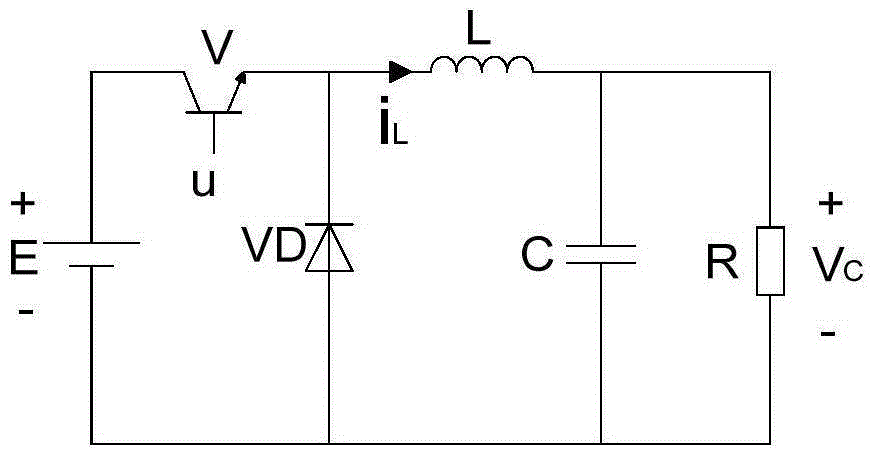
[0067] According to the circuit principle of the converter as figure 1 , taking the average value of the input voltage V of the Buck converter i is the control law u, then the mathematical model of the Buck converter is
[0068]
[0069] Among them, X 1 is the average value of the inductor current in one cycle, is the first-order derivative of the average value of the inductor current in one cycle, X 2 is the average value of the output voltage in one cycle, is the first-order derivative of the average value of the output voltage in one cycle, L is the filter inductance, C is the filter capacitor, R is the load resistance, d is the duty cycle of the controllable switch tube V, and u is the control law;
[0070] assuming...
specific Embodiment approach 2
[0099] Specific embodiment two: the difference between this embodiment and specific embodiment one is: the method for the design of the continuous non-singular terminal sliding mode controller is based on the average state model of the Buck converter, and the formula (6) in the step one The specific process of establishing the average state model of the Buck converter is as follows:
[0100] (1) When the controllable switch tube V is turned on, that is, m=1, the freewheeling diode VD is cut off under reverse bias, and the input DC power V i Connected in series with the inductance L, this is the stage of energy storage
[0101] Based on Kirchhoff's voltage and current laws, the differential equation of the Buck converter when it is turned on is obtained as
[0102]
[0103] where V i is the input DC voltage source, V is the controllable switch tube, m represents the working state, V 0 is the output voltage, VD is the freewheeling diode, L is the filter inductance, C is th...
specific Embodiment approach 3
[0113] Specific embodiment three: the difference between this embodiment and specific embodiment one or two is: the method for the design of the continuous non-singular terminal sliding mode controller is based on the average state model of the Buck converter, and the step two is to stabilize calculate:
[0114] Substitute the average state model of the Buck converter in formula (6) into the sliding mode arrival condition that is
[0115]
[0116] Substitute (9)-(14) into the above formula
[0117]
[0118] in, is the first derivative of the equivalent control law, is the second-order derivative of the value of the inductor current when the output DC voltage reaches the desired value, β is a parameter and β>0; p, q are parameters, and p>q>0, 1 hour, Constantly holds, when the system does not reach the sliding surface s n = 0, the sliding mode reaches the condition is always true, the system will converge to the sliding surface s in finite time n =0, the induc...
PUM
 Abstract
Description
Claims
Application Information
 - R&D
- Intellectual Property
- Life Sciences
- Materials
- Tech Scout
- Unparalleled Data Quality
- Higher Quality Content
- 60% Fewer Hallucinations
Browse by: Latest US Patents, China's latest patents, Technical Efficacy Thesaurus, Application Domain, Technology Topic, Popular Technical Reports.
© 2025 PatSnap. All rights reserved.Legal|Privacy policy|Modern Slavery Act Transparency Statement|Sitemap|About US| Contact US: help@patsnap.com


