
Magnetic clamping system for laser welding

A technology of laser welding and magnetic force, which is applied in laser welding equipment, welding equipment, welding equipment, etc., can solve the problems of excessive gap between the base plate and the reinforcing beam, high labor intensity of personnel, and bulky pressing mechanism, etc., to improve product quality and use Convenience and flexibility, the effect of improving production efficiency

Inactive Publication Date: 2015-12-30
北京金万众机械科技股份有限公司
View PDF7 Cites 3 Cited by
  • Summary
  • Abstract
  • Description
  • Claims
  • Application Information

AI Technical Summary

Problems solved by technology

However, due to the large size of the pressing plate and the large span of the beam, in order to ensure the strength of the beam, the pressing mechanism is relatively heavy
At the same time, when the traditional cylinder compression method is adopted, since the part between the two compression points is not subjected to the compression force, it is easy to cause the gap between the base plate and the reinforcing beam to exceed the standard, resulting in unqualified products
Moreover, the traditional clamping method also requires manual locking of the pressure plate and installation of the beam, which is labor-intensive and takes a long time for clamping, and the cylinder needs to be driven by compressed air, which consumes a lot of energy.

Method used


Image

  • Magnetic clamping system for laser welding
  • Magnetic clamping system for laser welding
  • Magnetic clamping system for laser welding

Examples


Embodiment Construction

[0018] The present invention will be described in detail below with reference to the accompanying drawings and examples.

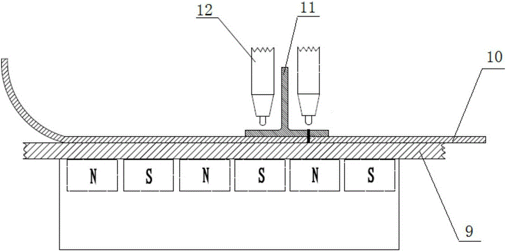
[0019] The wall panel of the train car comprises a plurality of base plates and a plurality of reinforcing beams, the base plates are sequentially overlapped and then welded together to form a bottom plate, and then the reinforcing beams are welded at a set position on the bottom plate. This embodiment provides a magnetic clamping system for laser welding in view of the large size of the substrate and the reinforcing beam and the characteristics that it is not easy to compress during welding. The clamping system can greatly simplify the clamping mechanism during laser welding and ensure uniform clamping force. , Improve product quality and yield.

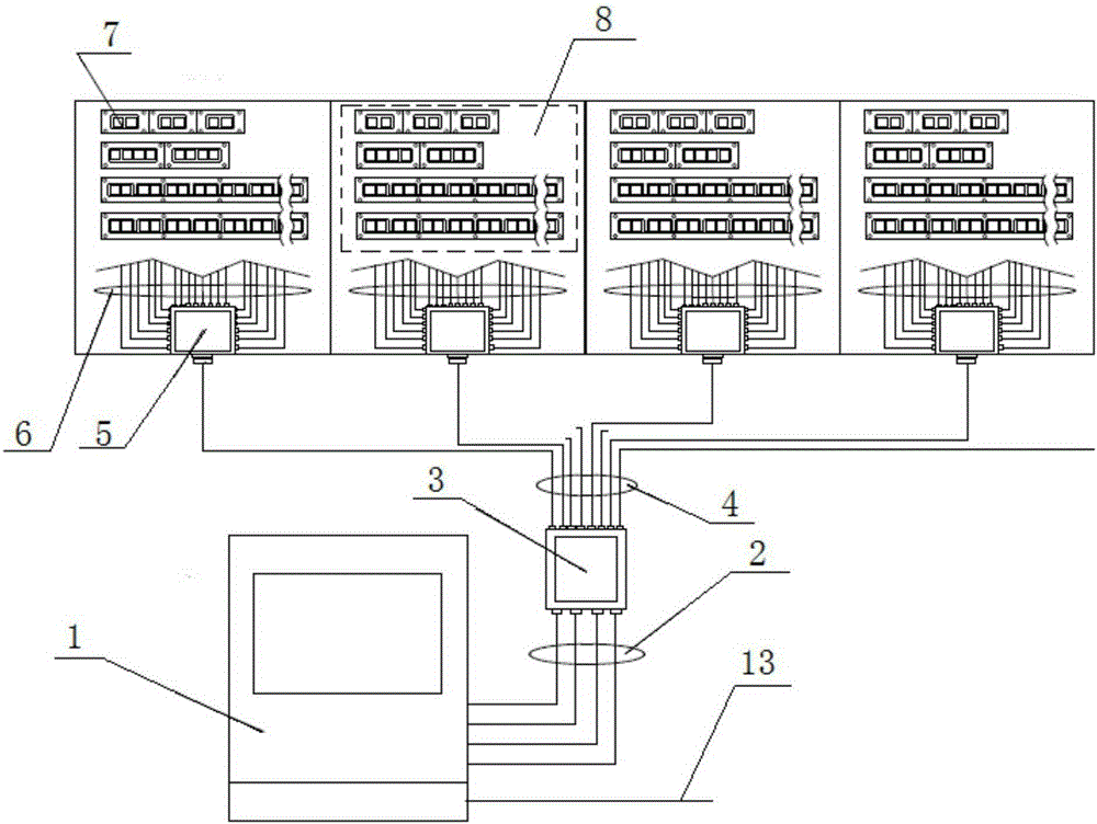
[0020] The laser welding magnetic clamping system includes: electronically controlled permanent magnet workbench 8, centralized control unit 1, main control cable 2, first-level junction box 3, sub-control cable...


PUM


Abstract

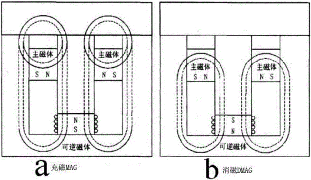
The invention discloses a magnetic clamping system for laser welding. The magnetic clamping system provides clamping force needed in welding through magnetic force of a permanent magnet material, is simple and reliable and can well remove gaps between parts and guarantee product quality. The magnetic clamping system comprises electric control permanent magnet worktables, a centralized control unit and a magnetization and demagnetization cable. Each electric control permanent magnet worktable is formed after arraying a plurality of electric permanent magnet modules according to the shape and welding position of a weldment, wherein the number and shape of the electric permanent magnet modules can be flexibly designed according to actual needs. The centralized control unit magnetizes or demagnetizes the electric control permanent magnet worktables independently through the magnetization and demagnetization cable to achieve modular control. In this way, different electric control permanent magnet worktables can be selected to be independently or simultaneously magnetized or demagnetized according to the sequence requirement of a welding technology, and accordingly the magnetic clamping system is convenient and flexible to use.

Description

technical field [0001] The invention relates to a clamping system, in particular to a magnetic force clamping system for laser welding. Background technique [0002] At present, when forming the wall panel of the train car, the base plate and the reinforcement beam are welded together by laser automatic welding. During welding, a pressing mechanism is required to compress the base plate and the reinforcement beam to make the gap between the base plate and the reinforcement beam Less than 0.2mm. Existing plate positioning and compaction mostly adopts a multi-point compaction method combining a press plate and a crossbeam cylinder. However, due to the large size of the pressing plate and the large span of the beam, in order to ensure the strength of the beam, the pressing mechanism is relatively heavy. At the same time, when the traditional cylinder compression method is adopted, since the part between the two compression points is not subjected to the compression force, it ...

Claims


Application Information

Patent Timeline
IPC IPC(8): B23K37/04B23K26/20
CPCB23K37/0461B23K26/20B23K37/0435B23K2101/006
Inventor 李少润董金锁张翌
Owner 北京金万众机械科技股份有限公司
Learn More