Method and device for recycling W and V from waste flue gas denitration catalyst

A denitrification catalyst and waste flue gas technology, applied in the direction of improving process efficiency, etc., can solve problems such as unsuitable for industrial production, high energy consumption, waste of reagents, etc.

Active Publication Date: 2015-12-30
CHINA HUADIAN ENG +1
View PDF9 Cites 11 Cited by
  • Summary
  • Abstract
  • Description
  • Claims
  • Application Information

AI Technical Summary

Problems solved by technology

[0004] The object of the present invention is to provide a method and device for recovering W and V from waste flue gas denitrification catalysts, which can effectively solve the problems in the prior art, especially the high-temperature roasting m

Method used


Image

  • Method and device for recycling W and V from waste flue gas denitration catalyst
  • Method and device for recycling W and V from waste flue gas denitration catalyst

Examples


Embodiment 1

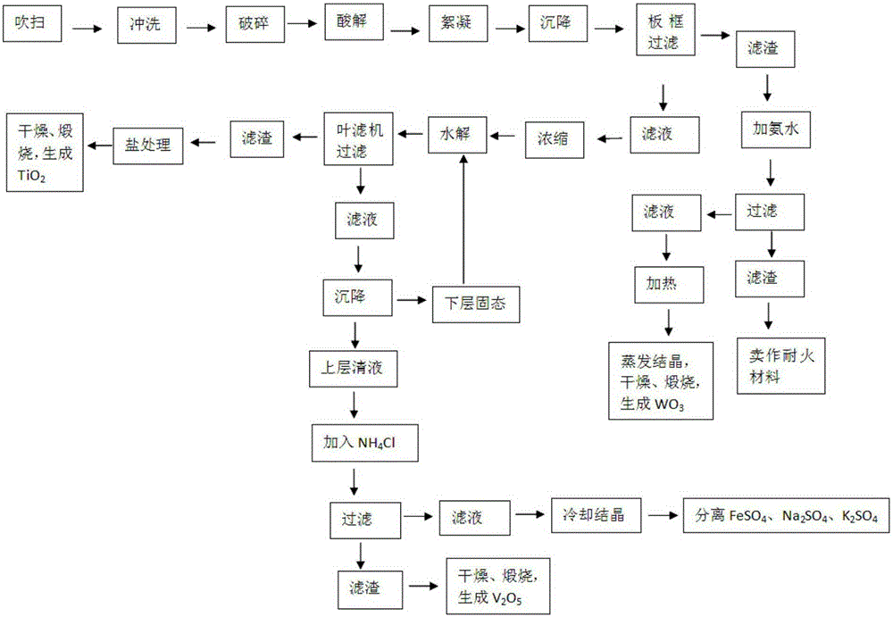
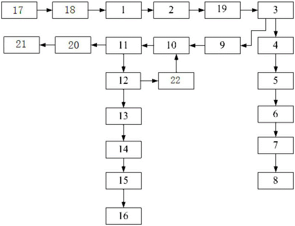
[0053] Embodiment 1 of the present invention: a method for recovering W and V from waste flue gas denitrification catalyst, such as figure 1 shown, including the following steps:

[0054] S01, blow the waste flue gas denitrification catalyst with compressed air for 20-23 minutes for each module to remove the dust in the channel;

[0055] S02, use a high-pressure water gun to flush the catalyst after dust removal, the flushing time of each module is 15-20min, and the pressure is 8-12Mpa, to further remove the dust in the channel;

[0056] S03, drying the washed catalyst;

[0057] S1, pulverizing the catalyst and adding concentrated sulfuric acid for acidolysis, adding water after acidolysis to obtain a titanyl sulfate solution; specifically including the following steps:

[0058] S11, crushing the catalyst into catalyst powder of 160-180 mesh;

[0059] S12, put the catalyst powder into the acid hydrolysis tank made of lead, add 88%-90% concentrated sulfuric acid according to t...

Embodiment 2

[0068] Embodiment 2: a kind of method that reclaims W and V from waste flue gas denitrification catalyst, such as figure 1 shown, including the following steps:

[0069] S01, blow the waste flue gas denitrification catalyst with compressed air, and blow each module for 15-20 minutes to remove the dust in the channel;

[0070] S02, use a high-pressure water gun to flush the catalyst after dust removal, the flushing time of each module is 20-25min, and the pressure is 5-8Mpa, to further remove the dust in the channel;

[0071] S03, drying the washed catalyst;

[0072] S1, pulverizing the catalyst and adding concentrated sulfuric acid for acidolysis, adding water after acidolysis to obtain a titanyl sulfate solution; specifically including the following steps:

[0073] S11, crushing the catalyst into 180-200 mesh catalyst powder;

[0074] S12, put the catalyst powder into a lead-made acidolysis tank, add 85% to 88% concentrated sulfuric acid according to the weight ratio of ca...

Embodiment 3

[0083] Embodiment 3: a kind of method that reclaims W and V from waste flue gas denitrification catalyst, such as figure 1 shown, including the following steps:

[0084] S01, blow the waste flue gas denitrification catalyst with compressed air for 23 to 30 minutes for each module to remove the dust in the tunnel;

[0085] S02, use a high-pressure water gun to flush the catalyst after dust removal, the flushing time of each module is 25-30min, and the pressure is 7-10Mpa, to further remove the dust in the channel;

[0086] S03, drying the washed catalyst;

[0087] S1, pulverizing the catalyst and adding concentrated sulfuric acid for acidolysis, adding water after acidolysis to obtain a titanyl sulfate solution; specifically including the following steps:

[0088] S11, pulverizing the catalyst into 190 mesh catalyst powder;

[0089] S12, put the catalyst powder into a lead-made acidolysis tank, add 90% to 92% concentrated sulfuric acid according to the weight ratio of cataly...


PUM


Abstract

The invention discloses a method and device for recycling W and V from a waste flue gas denitration catalyst. The method includes the steps that 1, the catalyst is crushed, concentrated sulfuric acid is added for acidolysis, water is added after acidolysis, and an oxygen titanium sulfate solution is obtained; 2, the oxygen titanium sulfate solution is filtered, filter residues are collected for standby application, the filter liquor is heated, concentrated and hydrolyzed, and a hydrolysis product is obtained; 3, the hydrolysis product is filtered, and settlement treatment is conducted on the filter liquor; 4, filtering is conducted after settlement treatment, supernatant liquid is taken, an excessive amount of NH<4>Cl is added to the clear liquid for a reaction, then filtering is conducted, and ammonium metavanadate sediment is obtained; the ammonium metavanadate sediment is calcined, and V<2>O<5> is obtained; 5, an excessive amount of ammonium hydroxide with the concentration being 10%-28% is added to the filter residues in step 2 for a reaction, and then filtering is conducted; the filter liquid is heated to be 80 DEG C-100 DEG C, and an ammonium paratungstate crystal is obtained; the ammonium paratungstate crystal is dried and calcined, and the WO<3> is obtained. By means of the method and device, the V<2>O<3> and the WO<3> which are both high in purity and recovery rate can be extracted from the waste flue gas denitration catalyst.

Description

technical field [0001] The invention relates to a recovery technology of a waste flue gas denitration catalyst, in particular to a method and a device for recovering W and V from a waste flue gas denitration catalyst. Background technique [0002] SCR denitrification technology is a necessary means for power plants to achieve ultra-clean emissions. As the core part of SCR denitrification technology, the catalyst will lose its activity due to wear or blockage during operation. Partially regenerable catalysts can continue to be used after regeneration, while non-regenerable catalysts face the situation of rational utilization and disposal (even if regenerable catalysts are regenerated 2 to 3 times, they cannot be regenerated and need to be rationally utilized and disposed of). At present, landfill is the way to dispose of waste denitration catalysts in foreign countries, but there are many thermal power plants in my country, and the amount of waste denitration catalysts produc...

Claims


Application Information

Patent Timeline
IPC IPC(8): C22B7/00C22B34/36C22B34/22
CPCY02P10/20
Inventor 苏军划胡永锋孙路长沈煜晖李苇林
Owner CHINA HUADIAN ENG
Why Eureka
Try Eureka