Phase Mask Switching Device

A phase mask and electronically controlled displacement technology, applied in the field of fiber grating, can solve the problems of difficult to control the relative position accurately, affecting the quality of writing gratings, slow writing gratings, etc., to achieve easy independent storage, good writing quality and repeatability, Horizontal distance consistent effect

A phase mask and electronically controlled displacement technology, applied in the field of fiber grating, can solve the problems of difficult to control the relative position accurately, affecting the quality of writing gratings, slow writing gratings, etc., to achieve easy independent storage, good writing quality and repeatability, Horizontal distance consistent effect

CN105204295BActive Publication Date: 2017-05-31SHANGHAI INST OF OPTICS & FINE MECHANICS CHINESE ACAD OF SCI +1

Image

  • Phase Mask Switching Device
  • Phase Mask Switching Device
  • Phase Mask Switching Device

Examples


Embodiment Construction

[0027] The present invention will be further described below in conjunction with the accompanying drawings, but the protection scope of the present invention should not be limited thereby.

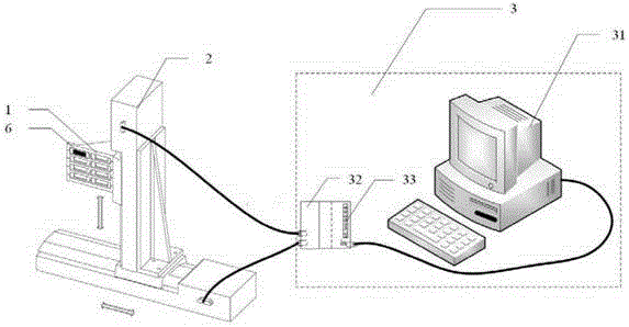
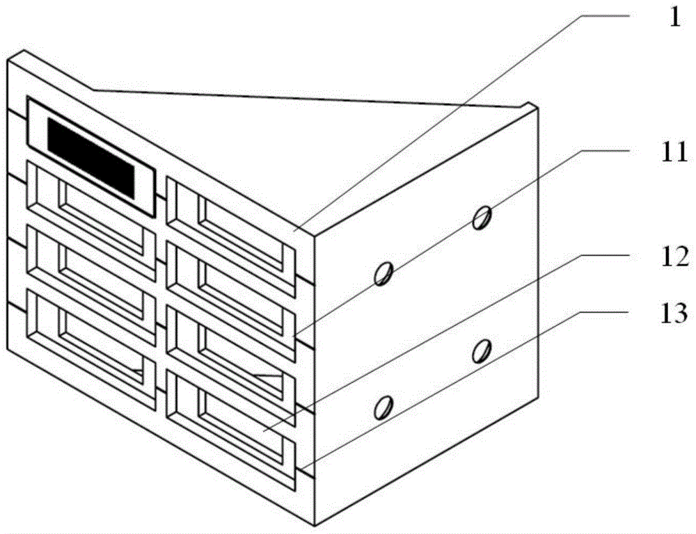
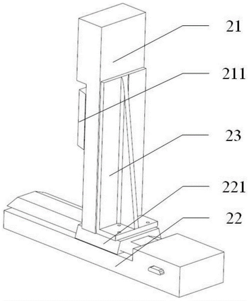
[0028] One of the implementations, the array type phase mask switching device, such as figure 1 As shown, the composition includes a phase mask fixture 1 , a one-dimensional electronically controlled displacement platform combination 2 and a control system 3 . like figure 2 As shown, the front side of the phase mask fixture 1 is used as a bottom plate, and has a plurality of rectangular grooves 11. The size and depth of the rectangular grooves 11 are determined by the size and thickness of the phase mask 6, and there is a certain size in the middle Rectangular light-transmitting holes 12 are regularly arranged to form an array. The array can be multiple rows and multiple columns, or single row and multiple columns or multiple rows and single column. A group of horizontal grooves on the f...


PUM


Abstract

The invention discloses an arrayed phase mask plate switching device and stepped phase mask plate switching device for etching gratings according to a phase mask plate writing method. The stepped phase mask plate switching device comprises a phase mask plate fixture or a phase mask plate fixture combination, two one-dimensional electric control displacement platforms, a transfer frame and a control system. Compared with the prior art, the arrayed phase mask plate switching device and stepped phase mask plate switching device have the advantages that the operation during etching of the optical fiber gratings is greatly simplified, the optical fiber gratings can be automatically etched, and the quality and the repeatability of grating etching can be improved.

Description

technical field [0001] The invention relates to an optical fiber grating, in particular to a phase mask switching device for writing a grating with a phase mask writing method. Background technique [0002] With the wide application of fiber Bragg grating in the fields of coherent optical communication, sensing and fiber laser, the demand for fiber Bragg grating is also increasing. Therefore, the automatic control of fiber Bragg grating writing is conducive to the mass production of fiber Bragg grating. Current methods of writing fiber gratings include the following: [0003] Standing wave interferometry was used in the early days. Its device is relatively simple, requiring a high content of germanium, a small core diameter, and the reflection wavelength of the grating is only determined by the wavelength of the writing light. The conditions for forming the grating are harsh, and the yield is low. It meets the practical requirements and is rarely used. [0004] Transverse ...

Claims


Application Information

Patent Timeline
31 May 2017
Publication
CN105204295B
IPC
G03F7/20; G02B6/02
Inventors
叶青; 王迪