Core assembly moulding sand mould structure for gearbox shell castings and core assembly moulding method

A core forming and gearbox technology, which is applied to casting molding equipment, molds, mold components, etc., can solve the problems of increasing the feeding pressure of the open riser, reducing the yield, and increasing the size of the open riser. The effect of increasing subsidized thermal insulation performance, shortening processing costs, and improving feeding efficiency

Active Publication Date: 2016-01-06
KOCEL STEEL
View PDF6 Cites 31 Cited by
  • Summary
  • Abstract
  • Description
  • Claims
  • Application Information

AI Technical Summary

Problems solved by technology

[0005] 1) The size of the open riser is large, and the shape of the boss on the upper end of the shell is covered in the riser, so that the shape of the boss cannot be directly cast on the upper end, and it needs to be processed and shaped, which increases the processing cost and cycle;
[0006] 2) The lower boss under the side wall of the shell adopts the feeding scheme of the hidden riser, which will increase the amount of sand eaten by the casting, the sand-iron ratio is too high, and the molding cost will increase. At the same time, the feeding pressure of the open riser will be increased, resulting in The size of the open riser becomes larger, the yield decreases, and the smelting cost increases;
[0007] 3) The entire casting scheme adopts solid collision modeling, only one piece can be produced in one box, and the production efficiency is low

Method used


Image

  • Core assembly moulding sand mould structure for gearbox shell castings and core assembly moulding method
  • Core assembly moulding sand mould structure for gearbox shell castings and core assembly moulding method
  • Core assembly moulding sand mould structure for gearbox shell castings and core assembly moulding method

Examples


Embodiment Construction

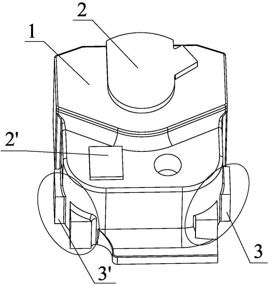
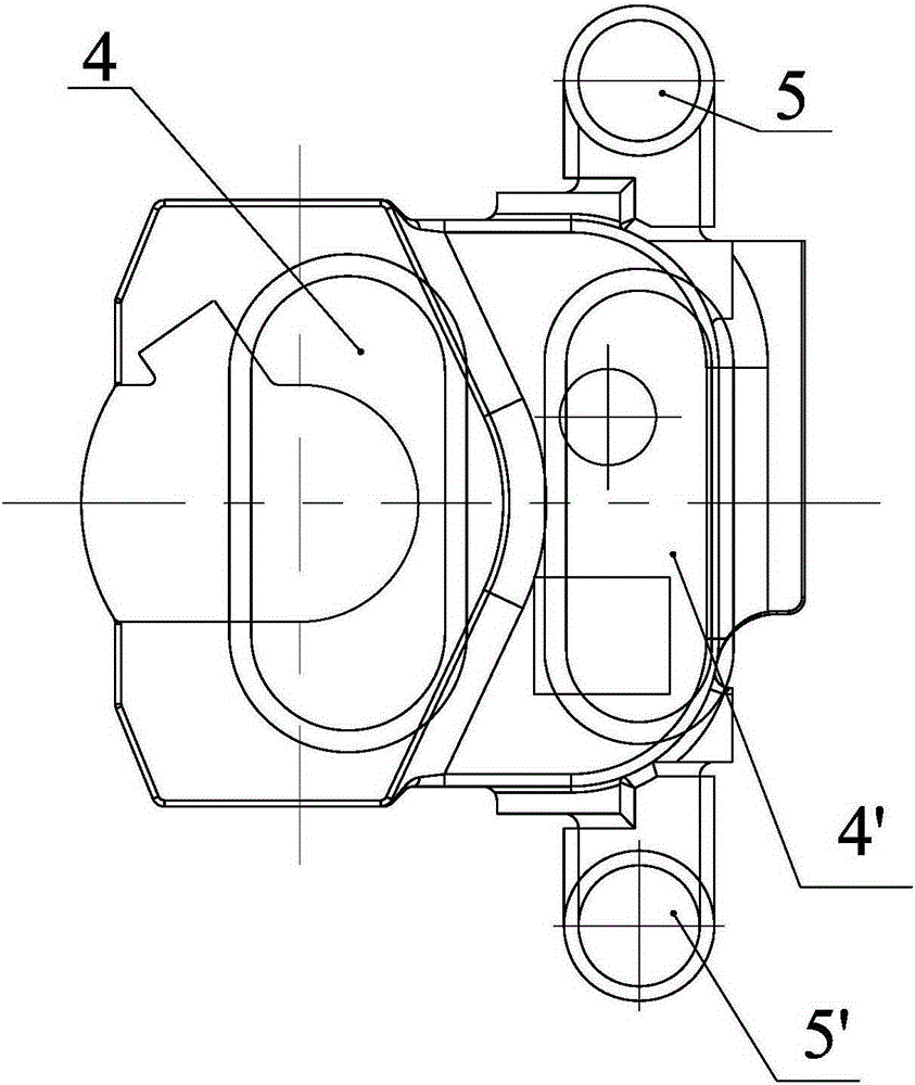
[0032] like Figure 4 — Figure 8 As shown, the core molding sand mold structure of the gearbox housing casting includes the inner cavity sand core 11, the outer contour sand core 12 and the pouring system sand mold 13, and the inner cavity sand core 11 and the outer contour sand core 12 are molded together. Finally, the cavity of the shell casting is formed. Several circular risers are arranged on the upper surface of the shell casting, and a number of cold irons 903 are set in the outer contour sand core between the circular risers. The side convex under the side wall of the casting A subsidy 905 is provided in the sand core corresponding to the outer contour of the table side, and an insulation layer is provided outside the subsidy 905; an inner sprue connected with the cavity of the casting is provided in the sand mold 13 of the gating system.

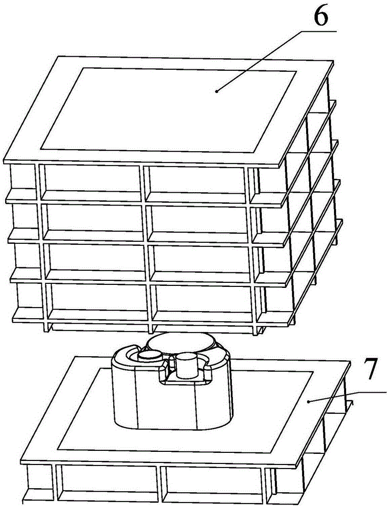
[0033] To facilitate precise packing, such as Image 6 and Figure 7 , in the outer contour sand core, the circular riser incl...


PUM

PropertyMeasurementUnit
sizeaaaaaaaaaa
thicknessaaaaaaaaaa

Abstract

The invention relates to a core assembly moulding sand mould structure for gearbox shell castings and a core assembly moulding method. The core assembly moulding sand mould structure for the gearbox shell castings comprises inner cavity sand cores, outer contour sand cores and a pouring system sand mould for core assembly moulding; The inner cavity sand cores and the outer contour sand cores are assembled to form mould cavities for the shell castings; the upper side of the upper end face of each shell casting is provided with multiple round feeders, and a plurality of chilling blocks are arranged in each outer contour sand core among the corresponding round feeders; supplement structures are arranged in each outer contour sand core corresponding to the sides of side bosses on the lower parts of the side walls of the corresponding shell casting, and an insulating layer is arranged on the outer side of each supplement structure; and ingates communicated with the mould cavities of the corresponding castings are arranged in the pouring system sand mould. According to the core assembly moulding sand mould structure disclosed by the invention, moulding and casting cost of the castings is reduced; the work load of subsequent machining of the castings is reduced; and the production efficiency is improved.

Description

technical field [0001] The invention relates to the field of casting technology, in particular to a core-forming sand mold structure and a core-forming method for castings of gearbox casings. Background technique [0002] Gearbox housing casting structure such as figure 1 As shown, compared with conventional castings, the structure is complex. The main structure is similar to a box with an opening downward. The wall thickness of the upper end surface 1 of the shell is 50~250mm, and there are many bosses 2, 2' on the end surface. The thickness of the side wall of the housing is only 38mm, and there are not several side bosses 3, 3' on the outer periphery below the side wall. [0003] In the prior art, the casting and feeding process of producing the gearbox housing casting is as follows: figure 2 As shown, two elliptical open risers 4, 4' are used for feeding on the upper surface of the shell, and the side bosses 3, 3' under the side wall of the shell are fed by hidden ris...

Claims


Application Information

Patent Timeline
Patent Type & Authority Applications(China)
IPC IPC(8): B22C9/02B22C9/22B22C9/08
Inventor 张立文马发仁王新军
Owner KOCEL STEEL
Why Eureka
Try Eureka