
Coil pipe type coal pyrolysis device

A coal pyrolysis, coil-type technology, used in special forms of dry distillation, indirect heating dry distillation, petroleum industry, etc., can solve problems such as poor heat exchange effect, achieve high gas density, high transportation efficiency, and reduce heat exchange area. Effect

Active Publication Date: 2016-01-06
CHANGZHENG ENG
View PDF8 Cites 1 Cited by
  • Summary
  • Abstract
  • Description
  • Claims
  • Application Information

AI Technical Summary

Problems solved by technology

However, it is an indisputable fact that its heat transfer effect is poor.

Method used


Image

  • Coil pipe type coal pyrolysis device

Examples


Embodiment Construction

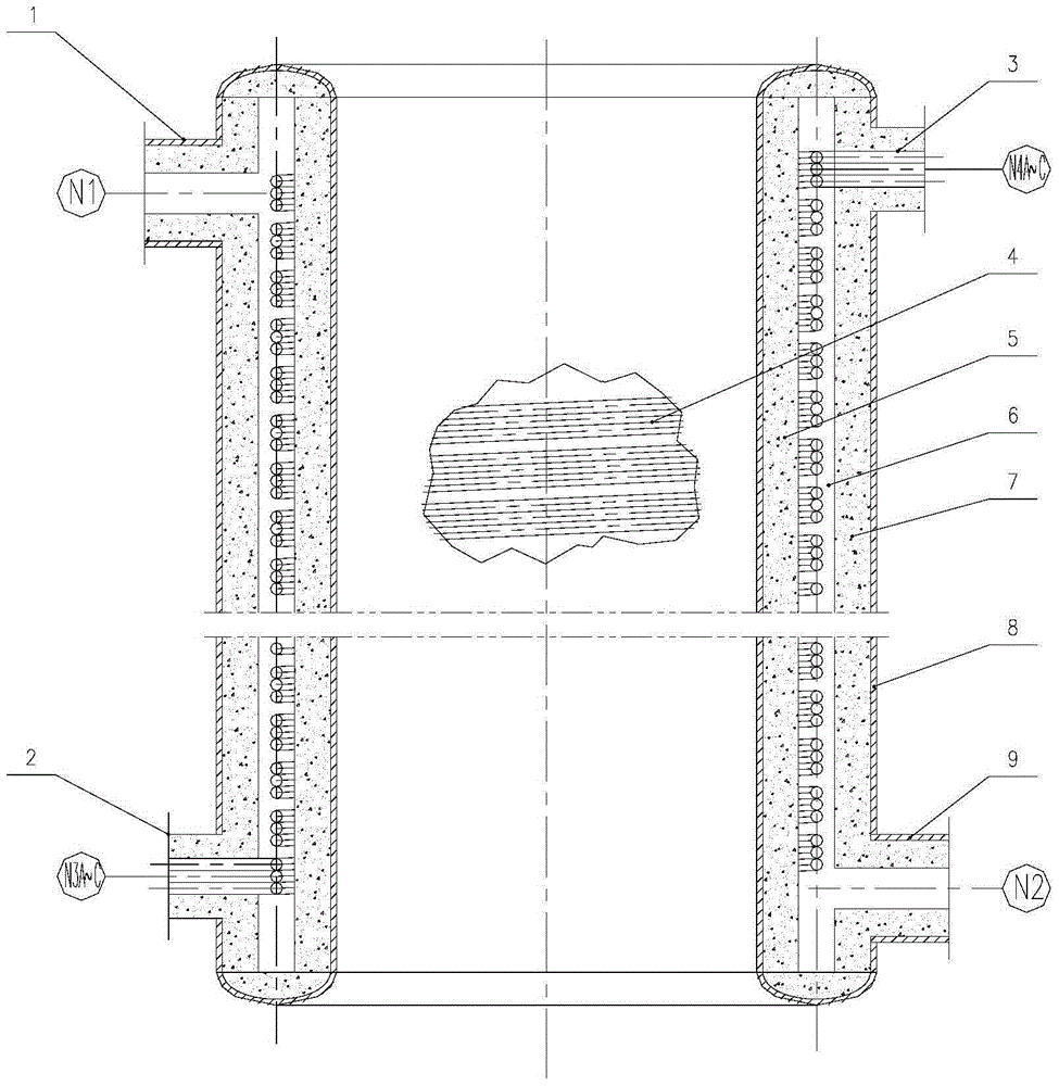
[0024] Attached below figure 1 The present invention is further described in detail, and the description in this part is only exemplary and explanatory, and should not have any limiting effect on the protection scope of the present invention.

[0025] Such as figure 1 As shown, the coil type coal pyrolysis device proposed by the present invention includes: flue gas inlet 1, coil inlet 2, coil outlet 3, heat exchange coil group 4, inner insulation layer 5, annular narrow cavity 6, outer The heat insulation layer 7, the shell 8, the flue gas outlet 9, the inner heat insulation layer 5 and the outer heat insulation layer 7 form an annular narrow cavity 6, and the heat exchange coil group 4 is placed in the annular narrow cavity 6, and the heat exchange coil group 4 It is composed of 3 sets of heat exchange coils. The radius of gyration of the heat exchange coils around the center line of the coal pyrolysis device is 80 times the inner diameter of the heat exchange coil tubes, an...


PUM


Abstract

The invention discloses a coal pyrolysis device, and particularly relates to a coil pipe type coal pyrolysis device. The coil pipe type coal pyrolysis device comprises a smoke gas inlet, an inner heat insulation layer, an annular narrow cavity, an outer heat insulation layer, a casing and a smoke gas outlet, wherein the annular narrow cavity is defined by the inner heat insulation layer and the outer heat insulation layer; the coil pipe type coal pyrolysis device also comprises a heat exchange coil pipe group, a coil pipe inlet and a coil pipe outlet; the heat exchange coil pipe group is positioned in the annular narrow cavity and is communicated with the coil pipe inlet and the coil pipe outlet. Through the design of installing the heat exchange coil pipe group in the annular narrow cavity in the heat insulation layer and the adoption of an indirect heat exchange form, a product generated through pyrolysis does not directly contact or mix with high-temperature smoke, so that high-temperature semicoke and pyrolysis gaseous products can be conveniently separated; the concentrations of tar, hydrogen and methane in the gaseous products are high; high economic benefits are realized.

Description

technical field [0001] The invention provides a coal pyrolysis device, in particular to a coil type coal pyrolysis device. Background technique [0002] my country is a big coal producing country in the world, and it is also a big coal consuming country. In terms of resource endowment, my country's primary energy has the characteristics of "poor oil, little gas, and rich coal". In 2010, my country's proven reserves of coal resources accounted for 93.3% of my country's fossil energy. Coal is currently the most reliable energy to ensure my country's energy security supply, and it is also the cheapest available energy at this stage. China's energy reserves, production and consumption structure determine that coal will remain the main energy source in my country for a period of time to come. [0003] The development of coal gasification technology has a history of more than 100 years, and has gradually formed a variety of technical schools such as fixed bed, entrained bed, and...

Claims


Application Information

Patent Timeline
IPC IPC(8): C10B53/04C10B47/18
Inventor 姜从斌王明坤章刚霍耿磊焦子阳马超
Owner CHANGZHENG ENG
Learn More