Hip dynamic stifling therapy machine
A treatment machine and hip technology, applied in physical therapy, other medical equipment, passive exercise equipment, etc., can solve problems such as hindering the popularization and utilization of treatment methods, poor treatment effect, and long process, and improve the quality of hip rehabilitation. The effect of design science
- Summary
- Abstract
- Description
- Claims
- Application Information
AI Technical Summary
Problems solved by technology
Method used
Image

Examples
Embodiment 1
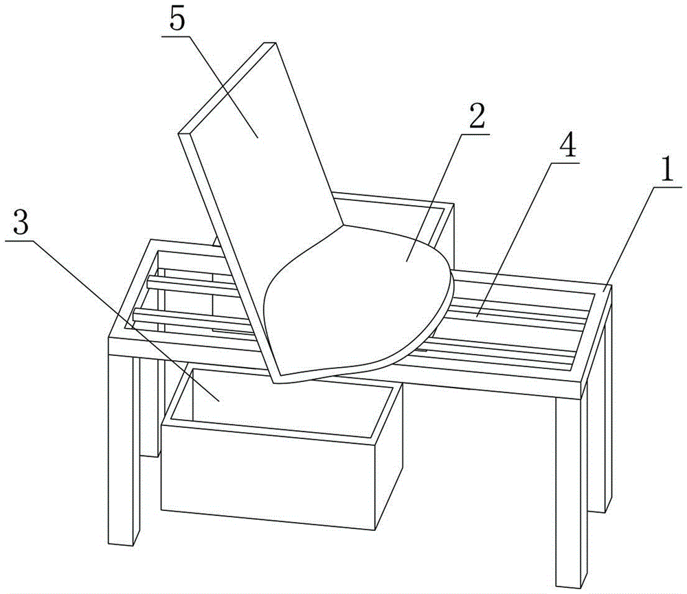
[0038] Such as figure 1 As shown, a hip dynamic fumigation treatment machine includes a bracket, a pelvic bracket 2 longitudinally arranged on the main slideway 4 on the bracket 1 and fumigation boxes 3 arranged on both sides of the pelvic bracket 2, the The pelvic bracket 2 is slidably connected to the main slideway 4, a backrest 5 that can be adjusted for sitting and lying is installed on the pelvic bracket 2, a headrest is installed on the backrest 5, and the pelvic bracket 2 is provided with The support part fits the physiological curvature of the ischia, sacrum, ischial tubercle, pubic bone and hip of the human body. The fumigation box 3 is provided with a soft movable box cover that can wrap around the hip of the human body, and the soft movable box cover is closed with the box body without air leakage to keep the fumigation temperature. The pelvic bracket 2 can move back and forth, adjust the sitting and lying position of the human body, realize dynamic adjustment, ens...
Embodiment 2
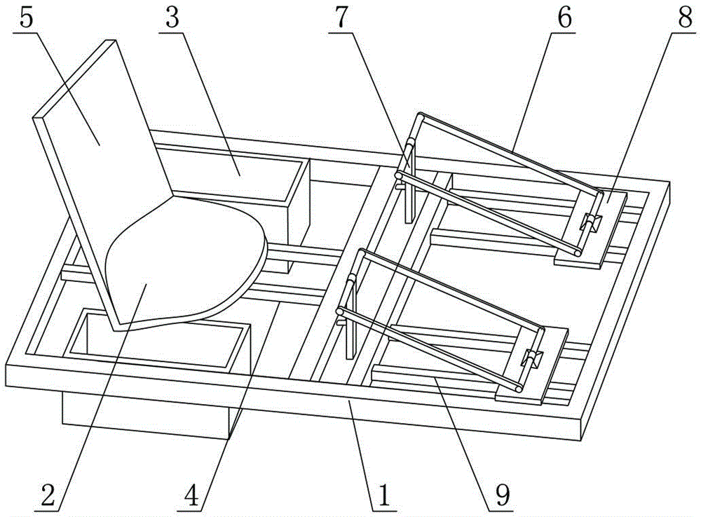
[0041] Such as figure 2As shown, the difference between this embodiment and Embodiment 1 is that it also includes a pair of lower limb functional exercise frames, and each of the lower limb functional exercise frames includes a lower limb support 6 set corresponding to the curve of the calf and a set of corresponding two lower limb functional exercise frames respectively. The auxiliary slideway, the elevating rod 7 which is arranged on the support and whose top end is hinged to the longitudinal front end of the lower limb support 6, and the slide plate 8 hinged to the longitudinal rear end of the lower limb support 6, the slide plate 8 is slidably connected to the auxiliary On slide 9. The lifting rod 7 drives the longitudinal front end of the lower limb support 6 to perform ups and downs, and at the same time drives the longitudinal rear end of the lower limb support 6 and the slide plate 8 to slide along the auxiliary slideway 9. This action is mainly used to drive the lowe...
Embodiment 3
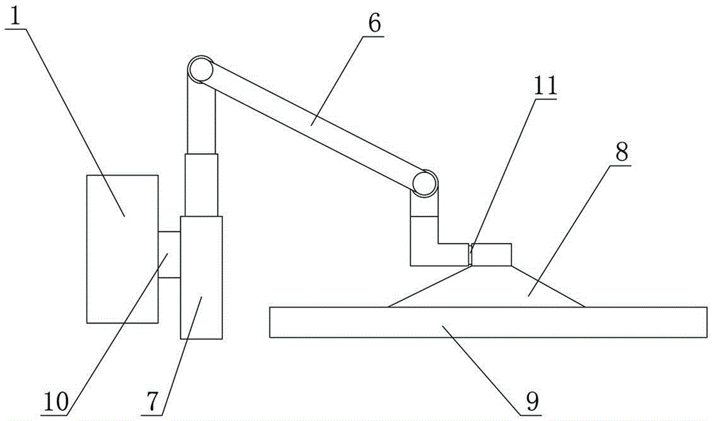
[0043] Such as image 3 As shown, the difference between this embodiment and Embodiment 2 is that: the elevating rod 7 has a first rotating part 10, and the elevating rod 7 is rotatably matched with the bracket through the first rotating part 10; 6. The longitudinal rear end has a second rotating part 11 through which the lower limb support 6 cooperates with the skateboard 8. The lower limb support 6 is connected between the first rotating part 10 and the second rotating part. 11 to swing in the transverse plane. The first rotating part 10 can be a rolling sleeve shaft. One end is sleeved on the lifting rod 7 and the upper and lower ends are fixed. It can only rotate and cooperate with the lifting rod 7 in the horizontal plane. Turning action; the second rotating part 11 can also be a rolling sleeve shaft, one end is sleeved on the longitudinal rear end of the lower limb support 6, hinged with the lower limb support 6, and one end is rotated and matched with the skateboard 8 ...
PUM
 Abstract
Description
Claims
Application Information
 - R&D
- Intellectual Property
- Life Sciences
- Materials
- Tech Scout
- Unparalleled Data Quality
- Higher Quality Content
- 60% Fewer Hallucinations
Browse by: Latest US Patents, China's latest patents, Technical Efficacy Thesaurus, Application Domain, Technology Topic, Popular Technical Reports.
© 2025 PatSnap. All rights reserved.Legal|Privacy policy|Modern Slavery Act Transparency Statement|Sitemap|About US| Contact US: help@patsnap.com