
Automatic laser cutting static electricity decarbonizing system and method for PI cover film

A technology of laser cutting and covering film, applied in the field of laser, can solve the problems of cutting and splicing accuracy affecting the quality of PI covering film, low production efficiency, affecting the quality of PI covering film, etc., to achieve the effect of automatic decarbonization of the surface

Active Publication Date: 2016-01-13
INNO LASER TECH CORP LTD +1
View PDF6 Cites 15 Cited by
  • Summary
  • Abstract
  • Description
  • Claims
  • Application Information

AI Technical Summary

Problems solved by technology

[0002] As a special engineering material, PI (Polyimide Film) cover film has been widely used in microelectronics, liquid crystal, separation membrane, laser, aviation, nanometer, aerospace and other fields. In industrial applications, PI cover film needs Carry out precise texture cutting. For large-format PI cover film cutting, the usual method is to use a laser galvanometer system combined with an X-Y motor module, that is, first use the laser galvanometer system for small-format cutting, and then move the X-Y motor module. Splicing and cutting, so as to realize large-format cutting, the cost of system equipment is high, and the cutting and splicing accuracy affects the quality of PI cover film; at the same time, after laser cutting, the cutting edge of PI cover film will be carbonized, and there will be dust on the surface, which will greatly affect PI coverage The quality of the film needs to be manually wiped and dedusted by using a liquid agent, and the production efficiency is low

Method used


Image

  • Automatic laser cutting static electricity decarbonizing system and method for PI cover film
  • Automatic laser cutting static electricity decarbonizing system and method for PI cover film
  • Automatic laser cutting static electricity decarbonizing system and method for PI cover film

Examples


Embodiment 1

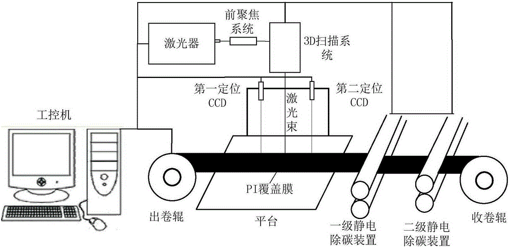
[0024] figure 1 It is a functional schematic diagram of a PI cover film automatic laser cutting electrostatic carbon removal system provided in this embodiment.

[0025] A PI cover film automatic laser cutting electrostatic decarbonization system, including: industrial computer, laser, 3D scanning system, positioning CCD, conveying device and electrostatic decarbonizing device, wherein the laser, 3D scanning system, positioning CCD, conveying device and the electrostatic carbon removal device are all connected to the industrial computer, and the conveying device is provided with a platform for placing the PI cover film to be processed. When the PI cover film is processed, the platform is processed from the 3D scanning system by the conveying device. Drive to the processing position of the electrostatic decarbonization device, wherein the conveying device includes an unwinding roller and a winding roller, and the positioning CCD is located above the processing position of the 3...

Embodiment 2

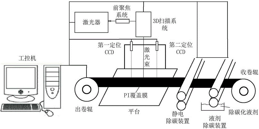
[0034] Such as figure 2 As shown, as another embodiment, it also includes a liquid agent carbon removal device, the liquid agent carbon removal device is located between the electrostatic carbon removal device and the winding roll, and the liquid agent carbon removal device includes an upper roller and a lower roller , the lower roller is controlled by an industrial computer to automatically add a decarbonization liquid agent. Different from the two-stage electrostatic decarbonization device, this embodiment adopts a two-stage decarbonization device that combines an electrostatic decarbonization device and a liquid agent decarbonization device. The carbon removal devices are combined and complement each other, and the carbon removal effect is better.

[0035] In this embodiment, the liquid agent carbon removal device is a roll-to-roll carbon removal device, which removes the carbonized dust on the cutting edge of the PI cover film through rolling friction and the action of th...

Embodiment 3

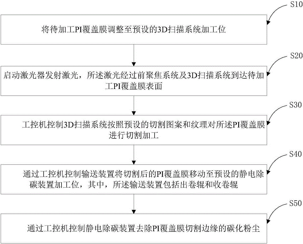
[0037] Such as image 3 Shown, a kind of PI covering film automatic laser cutting electrostatic decarburization method, comprises:

[0038] S10. Adjust the PI cover film to be processed to the preset processing position of the 3D scanning system;

[0039] S20, start the laser to emit laser, and the laser reaches the surface of the PI cover film to be processed through the front focusing system and the 3D scanning system;

[0040] S30, the industrial computer controls the 3D scanning system to cut and process the PI cover film according to the preset cutting pattern and texture;

[0041] S40. Using the industrial computer to control the conveying device to move the cut PI cover film to the preset processing position of the electrostatic decarbonization device, wherein the conveying device includes a winding roller and a winding roller;

[0042] S50. Control the electrostatic carbon removal device through the industrial computer to remove the carbonized dust on the cutting edg...


PUM


Abstract

The invention relates to the technical field of lasers, in particular to an automatic laser cutting static electricity decarbonizing system and method. The system comprises an industrial personal computer, a laser device, a 3D scanning system, positioning CCDs, a conveying device and a static electricity decarbonizing device. The laser device, the 3D scanning system, the positioning CCDs, the conveying device and the static electricity decarbonizing device are all connected with the industrial personal computer. The conveying device is provided with a platform for containing the PI cover film to be machined. When the PI cover film is machined, the platform is driven by the conveying device to move to a static electricity decarbonizing device machining station from a 3D scanning system machining station. The conveying device comprises an unrolling roller and a rolling roller. The positioning CCDs are used for monitoring and positioning the 3D scanning system machining station. Through automatic control over the laser device, the 3D scanning system, the positioning CCDs, the conveying device and the static electricity decarbonizing device by the industrial personal computer, large areas of the PI cover film can be cut automatically, and meanwhile automatic decarbonizing of the surface is achieved.

Description

technical field [0001] The invention relates to the field of laser technology, in particular to an electrostatic carbon removal system and method for automatic laser cutting of PI covering film. Background technique [0002] As a special engineering material, PI (Polyimide Film) cover film has been widely used in microelectronics, liquid crystal, separation membrane, laser, aviation, nanometer, aerospace and other fields. In industrial applications, PI cover film needs Carry out precise texture cutting. For large-format PI cover film cutting, the usual method is to use a laser galvanometer system combined with an X-Y motor module, that is, first use the laser galvanometer system for small-format cutting, and then move the X-Y motor module. Splicing and cutting, so as to realize large-format cutting, the cost of system equipment is high, and the cutting and splicing accuracy affects the quality of PI cover film; at the same time, after laser cutting, the cutting edge of PI co...

Claims


Application Information

Patent Timeline
Patent Type & Authority Applications(China)
IPC IPC(8): B23K26/38B23K26/70B23K26/04B23K26/402B08B7/00
CPCB08B7/00B23K26/04B23K26/38
Inventor 雷志辉林思引杨焕
Owner INNO LASER TECH CORP LTD
Learn More