Automatic box making device and method
An automatic manufacturing and equipment technology, which is applied in container manufacturing machinery, box manufacturing operations, rigid/semi-rigid container manufacturing, etc. It can solve the problems of low production speed and efficiency, large footprint, and the inability to further improve the processing efficiency of the whole system, etc. problem, achieve the effect of improving processing speed and production efficiency and reducing occupied space
- Summary
- Abstract
- Description
- Claims
- Application Information
AI Technical Summary
Problems solved by technology
Method used
Image

Examples
Embodiment 1
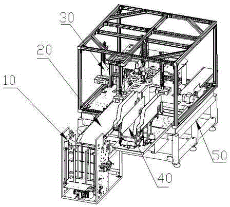
[0043] Such as figure 1 , is a structural schematic diagram of an automatic box-making equipment according to one embodiment of the present invention. The equipment is used to produce heaven and earth cover-shaped boxes, including a pasting machine 10, a conveyor belt 20, a forming machine 30, a jigsaw machine 40, a machine Rack 50. The gluing machine 10 is located at the forefront of the automatic box-making equipment. One end of the conveyor belt 20 is close to the gluing machine 10 to transport the glued face paper coming from the gluing machine 10, and the other end is adjacent to the forming machine 30. The jigsaw machine 40 is arranged parallel or perpendicular to the conveyor belt 20 and is fixed on the frame 50 .
[0044]The gluing machine 10 adopts a common structure in the industry, and its main components include a paper feeding mechanism, a feeder mechanism and a gluing mechanism. The paper feeding mechanism is responsible for feeding the facial paper, the feeder...
Embodiment 2
[0061] An automatic box-making device according to another embodiment of the present invention, the action before the shovel edge folding is completed is the same as that of the first embodiment, the difference lies in the shovel edge folding action and after. The shovel edge folding action of the present embodiment adopts the carton shovel edge forming mechanism 60 commonly used in the industry to complete, as Figure 8 . The brushed inner box is moved from the conversion platform to the forming station by the box holding mechanism. The inner box adopts the double-mode clamping method of the upper inner mold and the lower inner mold. Both the upper and lower inner molds are driven by motors. By controlling the upper and lower inner molds The rotation angle of the motor lowers the inner box to the scraper position. The long side blade and the short side blade and the four box holding heads are all located on the same level. The box-holding machine head first hugs the long si...
PUM
 Abstract
Description
Claims
Application Information