Biomass fuel combustion device

A biomass fuel and combustion device technology, applied in the direction of solid fuel combustion, combustion methods, combustion equipment, etc., can solve the problems of low combustion efficiency, heat loss, complex structure, etc., to improve combustion efficiency, reduce occupied space, avoid coking effect

Inactive Publication Date: 2016-01-13
广西节得乐生物质能源科技有限公司
View PDF7 Cites 2 Cited by
  • Summary
  • Abstract
  • Description
  • Claims
  • Application Information

AI Technical Summary

Problems solved by technology

[0004] The purpose of the present invention is to provide a biomass fuel combustion device, which overcomes the defects of low combustion efficiency, complex structure, and large heat loss of the p

Method used


Image

  • Biomass fuel combustion device
  • Biomass fuel combustion device
  • Biomass fuel combustion device

Examples


Embodiment 1

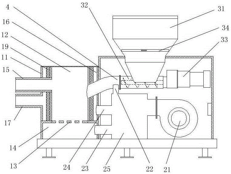
[0028] like figure 1 As shown, the biomass fuel combustion device provided in this embodiment includes a combustion chamber, a blast device, and a feeding device, and the charging device includes a feeding pipe 4; the combustion chamber includes a casing 11, a furnace 12, and a fire grate 13 , ash box 14 and fire outlet pipe 15; an air-cooled interlayer 16 is provided between the shell 11 and the furnace 12; a fire grate 13 and ash box 14 are arranged below the furnace 12; the fire outlet pipe 15 is arranged on the combustion chamber One side of the chamber communicates with the furnace 12, and stretches out after passing through the air-cooled interlayer 16 and the shell 11;

[0029] Described blower device comprises fan 21, air duct I22, air duct II23, air duct III24, and described fan 21 communicates with air duct I22, air duct II23 and air duct III24 respectively; 4 connected; the air duct II 23 communicates with the ash box 14; the air duct III 24 communicates with the a...

Embodiment 2

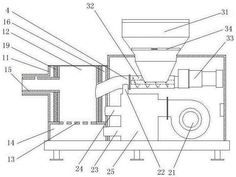
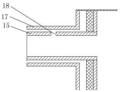
[0035] like figure 2 , 3 As shown, the biomass fuel combustion device provided in this embodiment includes a combustion chamber, a blast device, and a feeding device, and the charging device includes a feeding pipe 4; the combustion chamber includes a casing 11, a furnace 12, and a fire grate 13 , ash box 14 and fire outlet pipe 15; an air-cooled interlayer 16 is provided between the shell 11 and the furnace 12; a fire grate 13 and ash box 14 are arranged below the furnace 12; the fire outlet pipe 15 is arranged on the combustion chamber One side of the chamber communicates with the furnace 12, and stretches out after passing through the air-cooled interlayer 16 and the shell 11;

[0036] Described blower device comprises fan 21, air duct I22, air duct II23, air duct III24, and described fan 21 communicates with air duct I22, air duct II23 and air duct III24 respectively; 4 connected; the air duct II 23 communicates with the ash box 14; the air duct III 24 communicates with...


PUM


Abstract

The invention provides a biomass fuel combustion device. The biomass fuel combustion device comprises a combustion chamber, a blower device and a feeding device. The feeding device comprises a feeding pipe. The combustion chamber comprises a shell, a hearth, a grate, an ash box and a flame outlet pipe. An air cooling interlayer is arranged between the shell and the hearth. The grate and the ash box are arranged under the hearth. The flame outlet pipe is arranged at one side of the combustion chamber and communicated with the hearth and stretches out after penetrating through the air cooling interlayer and the shell. The blower device comprises a draught fan, an air pipe I, an air pipe II and an air pipe III. The draught fan is communicated with the air pipe I, the air pipe II and the air pipe III. The air pipe I is communicated with the feeding pipe. The air pipe II is communicated with the ash box. The air pipe III is communicated with the air cooling interlayer. According to the biomass fuel combustion device, the defects that in the prior art, a combustion device is low in combustion efficiency, complicated in structure and large in heat loss are overcome; the biomass fuel combustion device has the characteristics that the structure is compact and simple, oxygen supply is sufficient, the particle combustion efficiency is high, and the heat transferring effect is good.

Description

technical field [0001] The invention relates to the field of combustion equipment, in particular to a biomass fuel combustion device. Background technique [0002] Biomass pellet fuel is a new type of energy, mainly used for gasification and combustion. Studies have shown that biomass pellet fuel has low sulfur and nitrogen content, is easy to ignite, has high combustion efficiency, and has a small ash content. After combustion, the emissions of SO2, NOX and soot are much smaller than those of fossil fuels. clean energy. [0003] At present, biomass combustion in the market is generally used in boiler equipment. The traditional biomass burner furnace needs to be water-cooled, because the heat loss caused by the water-cooling system accounts for about 15% of the total heat, so the efficiency of heat energy use is very low. It also wastes precious water resources. At the same time, when the biomass fuel is gasified and burned in the furnace, the fuel is often not fully burn...

Claims


Application Information

Patent Timeline
IPC IPC(8): F23B40/00F23K3/00
Inventor 陈战李华严黄海纲赖世耀
Owner 广西节得乐生物质能源科技有限公司
Why Eureka
Try Eureka