

Automatic boom road-header space pose detection system and measurement method thereof
A cantilever roadheader and automatic detection technology, which is applied in the directions of measuring devices, surveying and navigation, navigation, etc., can solve problems such as affecting the direction of the control roadway, and achieve the effects of simple structure, low cost, and improved working environment.
- Summary
- Abstract
- Description
- Claims
- Application Information
AI Technical Summary
Problems solved by technology
Method used
Image

Examples
Embodiment Construction
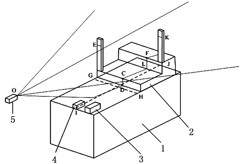
[0015] Such as figure 1As shown, a cantilever-type roadheader space posture automatic detection system includes a structured light laser 5 installed on the roof of the roadway, a mining explosion-proof camera 4 installed on the cantilever-type roadheader 1 body, and an image processing platform 3 and a step structure 2, the step structure 2 includes upper and lower steps, the length and height of the two steps are scalable, the step structure 2 is installed on the front end of the upper surface of the cantilever boring machine 1, and the direction of the symmetrical axis of the step structure 2 Consistent with the direction of the longitudinal symmetry axis of the fuselage; the structured light laser 5 is provided with a horizontal indicator, which is installed on the roof of the roadway 15 meters away from the section of the tunneling roadway, and the structured light laser 5 projects two vertical The fan laser is projected on the step structure 2 to form a cross-shaped struc...
PUM
| Property | Measurement | Unit |
|---|---|---|
| Height | aaaaa | aaaaa |
| Width | aaaaa | aaaaa |
Abstract
Description
Claims
Application Information