
A kind of plasma electrode and its manufacturing method

A technology of plasma electrode and manufacturing method, which is applied to plasma welding equipment, manufacturing tools, welding medium, etc., can solve the problems of unsatisfactory conductivity and product appearance of dispersed copper, increased product cost, long brazing time, etc., and can achieve surface quality. The effect of perfection, material cost reduction, brazing time reduction

Active Publication Date: 2017-08-25
常州特尔玛科技股份有限公司
View PDF1 Cites 0 Cited by
  • Summary
  • Abstract
  • Description
  • Claims
  • Application Information

AI Technical Summary

Problems solved by technology

The disadvantages are: 1. The cost of the product is greatly increased; 2. The brazing time is longer, and subsequent processing is required; 3. The conductivity of dispersed copper and the appearance of the product are not ideal

Method used


Image

  • A kind of plasma electrode and its manufacturing method
  • A kind of plasma electrode and its manufacturing method
  • A kind of plasma electrode and its manufacturing method

Examples


Embodiment 1

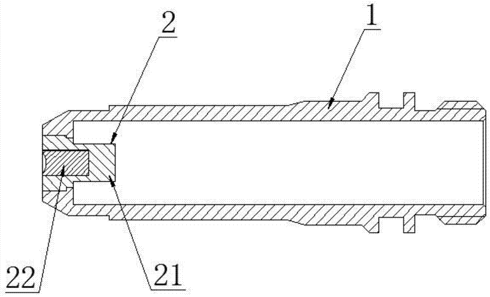
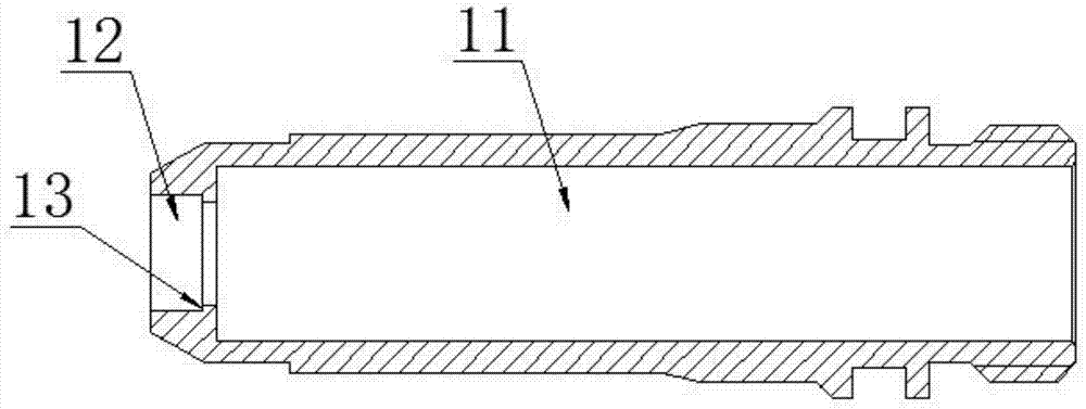
[0039] See Figure 1 to Figure 3 , The plasma electrode of this embodiment includes an electrode body 1 and a brazed inner core 2 .

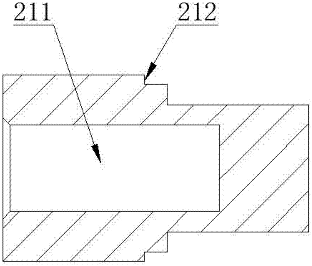
[0040] The inside of the electrode body 1 is provided with a cooling hole 11 , and the head of the electrode body 1 is provided with an inner core hole 12 communicating with the cooling hole 11 . The brazed inner core 2 is welded in the inner core hole 12 of the electrode main body 1 . The brazed inner core 2 includes an electrode main body inner core 21 and an electrode emitter 22 . The material of the electrode emitter 22 is hafnium, zirconium, tungsten and the like. The inner core 21 of the electrode main body is provided with a brazing hole 211 . The electrode emitter 22 is brazed in the brazing hole 211 of the electrode body inner core 21 . The electrode body 1 and the electrode body inner core 21 of the brazed inner core 2 are all made of oxygen-free copper. The outer wall of the electrode main body inner core 21 of the brazing type i...

Embodiment 2

[0052] See Image 6 This embodiment is basically the same as Embodiment 1, except that the outer limiting structure 212 of the inner core 21 of the electrode body and the inner limiting structure 13 of the electrode body 1 are wave-like structures that can be attached to each other.

Embodiment 3

[0054] See Figure 7 This embodiment is basically the same as Embodiment 1, except that the outer limiting structure 212 of the inner core 21 of the electrode body and the inner limiting structure 13 of the electrode body 1 are beveled structures that can be attached to each other.


PUM


Abstract

The invention discloses a plasma electrode and a manufacturing method of the plasma electrode. The plasma electrode comprises an electrode body and a brazing type inner core. A cooling hole is formed in the electrode body. An inner core hole communicated with the cooling hole is formed in the head of the electrode body. The brazing type inner core is welded in the inner core hole of the electrode body. The brazing type inner core comprises an electrode body inner core and an electrode transmitter. A brazing hole is formed in the electrode body inner core. The electrode transmitter is welded in the brazing hole in the electrode body inner core. The plasma electrode and the brazing type inner core of the plasma electrode are of split structures, and the electrode body inner core is connected with the transmitter in a brazing manner and is then assembled with the electrode body. The influences of the high temperature on the overall structure of the electrode are small during welding, even if the electrode body inner core deforms due to the high temperature in the brazing process, no influence is caused on the overall shape of the product, and the overall product quality cannot be influenced.

Description

technical field [0001] The invention relates to an electrode for plasma cutting equipment and a manufacturing method thereof. Background technique [0002] Plasma electrodes usually include common cutting electrodes and mosaic plasma electrodes. Ordinary cutting electrodes are directly press-fit the emitter into the hole on the end surface of the conductor. The process is simple and the processing cost is low, but the life is short and it is prone to poor contact. In the interference press-fit connection, the size of the interference is extremely important. If the interference is too large, the material cannot withstand it, and cracks will occur; if the interference is too small, the heat will be large, and the resistance will be too large due to poor contact, and the function will not be realized. The inlaid plasma electrode inlays a silver ring in the shaft hole of the conductor, and the emitter is assembled into the shaft hole of the conductor by press-fitting. Compared ...

Claims


Application Information

Patent Timeline
Patent Type & Authority Patents(China)
IPC IPC(8): B23K35/06B23K10/00B23P15/00
CPCB23K10/00B23K35/0205B23P15/00
Inventor 戴万良李文琦王新霞黄彩红
Owner 常州特尔玛科技股份有限公司
Learn More