Wind-solar complementary cold and hot pneumoelectric new energy system of compressed air energy storage

A technology of compressed air energy storage and compressed air, which is applied in the field of new energy utilization system engineering, can solve problems such as affecting the stability of power supply and power quality, raising the cost of clean energy, and poor economy, so as to improve technical efficiency and economic benefits and save energy. Equipment and land investment, reducing the effect of strong dependence

Active Publication Date: 2016-01-20
贡茅
View PDF4 Cites 6 Cited by
  • Summary
  • Abstract
  • Description
  • Claims
  • Application Information

AI Technical Summary

Problems solved by technology

[0003] The trouble with the first method is that the wind power plant can instantly reach the peak power supply when there is strong wind, but it will stop generating power when there is no wind. Similarly, when dark clouds cover the photovoltaic array, the output of the solar panel may be reduced by hundreds of thousands of kw. , such large fluctuations affect the stability of power supply and the power quality threatens the security of the power grid. A large number of reliable energy peaking power stations are used as "backups", which greatly increases the cost of using clean energy
[0004] The second method is less economical and is only suitable for unattended places with high value and low power such as satellites, surveying, and communication base stations. It cannot store electricity for power supply on a large scale. "Strike", December 4, 2013, Information Times reported "Ten thousand yuan energy-saving street lamps are "blind" for several roads"
Other large-scale compressed air energy storage power stations have been successfully operated in Europe and the United States, but the fly in the ointment is that the compressed air they store is converted from the generated electric energy to drive the air compressor, and there is no It is directly used by users, and then converted into electricity again, which wastes energy by repeated transformation

Method used


Image

  • Wind-solar complementary cold and hot pneumoelectric new energy system of compressed air energy storage
  • Wind-solar complementary cold and hot pneumoelectric new energy system of compressed air energy storage
  • Wind-solar complementary cold and hot pneumoelectric new energy system of compressed air energy storage

Examples


specific Embodiment

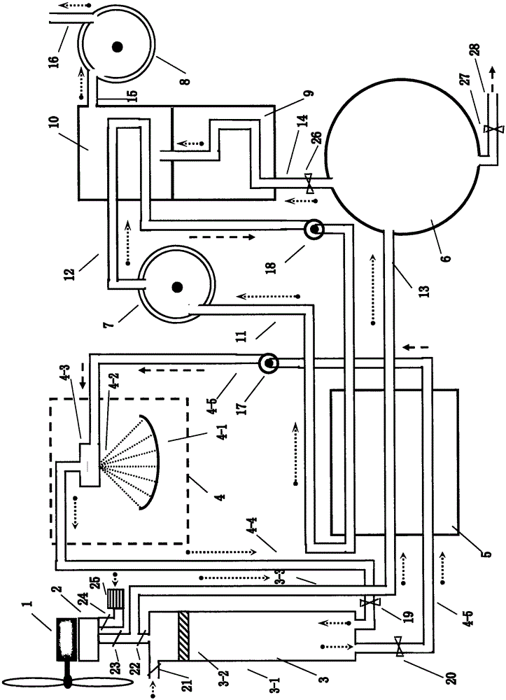
[0028] Specific embodiment: the wind-solar complementary cooling, heating, gas-electricity new energy system of compressed air energy storage can be divided into two subsystems: "compressed air expansion gas turbine power generation sub-system" and "low boiling point working fluid vaporization expansion gas turbine power generation sub-system" The composition and mode of operation have been described in the above "technical solution", because it is a specific embodiment, the following points need to be added:

[0029] 1. What is added to the "solar heating boiler" (4) in the "compressed air expansion gas turbine power generation system" is: water; what is added to the "low boiling point working fluid vaporization expansion steam turbine power generation system" is: ethyl chloride Alkane (or other haloalkane).

[0030] 2. Water is water vapor in a heated state, and liquid water in a condensed state; ethyl chloride (or other halogenated alkanes) is a vapor state in a heated stat...


PUM


Abstract

The invention discloses a wind-solar complementary cold and hot pneumoelectric new energy system of compressed air energy storage and relates to the field of new energy utilization system engineering. The wind-solar complementary cold and hot pneumoelectric new energy system can be divided into the two subsystems of a compressed air expansion pneumatic wheel electricity generation subsystem and a low boiling point working medium vaporization expansion pneumatic wheel electricity generation subsystem. The purposes of wind-solar complementary cold and hot pneumoelectric new energy system are that 1, a novel technical route is found out, and an energy conversion chain is shortened as far as possible; and 2, a novel complementary energy storage mode is adopted to improve the overall efficiency of new energy utilization. The wind-solar complementary cold and hot pneumoelectric new energy system has four characteristics.

Description

technical field [0001] The invention relates to the field of new energy utilization system engineering, mainly to make full use of various energy forms, shorten the energy conversion chain, adopt a new complementary energy storage mode, and improve the overall efficiency. Background technique: [0002] The existing wind-solar hybrid technology first converts wind energy and solar energy into electrical energy. Due to the inherent intermittent and fluctuating nature of wind-solar power generation, the reduced reliability of the power grid brings great troubles to power transmission and power consumption that require stable operation. For this reason, there are currently two commonly used solutions: one is to tap the peak-shaving capacity of existing power stations, and the other is to use extremely expensive batteries for energy storage. [0003] The trouble with the first method is that the wind power plant can instantly reach the peak power supply when there is strong wind,...

Claims


Application Information

Patent Timeline
Patent Type & Authority Applications(China)
IPC IPC(8): F01K25/10F01D15/10F25B29/00
Inventor 贡茅
Owner 贡茅
Why Eureka
Try Eureka