
A kind of manufacturing method of fingerprint collection optical fiber panel

An optical fiber panel and a technology for manufacturing methods, which are applied in the direction of optical fiber bundles, manufacturing tools, glass manufacturing equipment, etc., can solve the problems of unfavorable promotion and use of fingerprint recognition systems, expensive materials, and complicated manufacturing, so as to meet market competition needs and reduce material costs. The effect of low and simplified production process

Active Publication Date: 2018-08-28
GUANGZHOU HONSUN OPTOELECTRONICS
View PDF5 Cites 0 Cited by
  • Summary
  • Abstract
  • Description
  • Claims
  • Application Information

AI Technical Summary

Problems solved by technology

[0004] Existing fiber optic panel products are mainly used in high-end fields such as microscopic night vision, physical research, and medical treatment. They have high requirements for raw materials, and they have to go through processes such as wire drawing, board arrangement, melting, rolling, cutting, and finishing, and the materials are expensive. , complex production, high cost
[0005] For the fingerprint recognition system, low price is an important factor of market competition. The production method of the existing optical fiber panel is not conducive to the popularization and use of its fingerprint recognition system due to its high cost.

Method used


Image

  • A kind of manufacturing method of fingerprint collection optical fiber panel
  • A kind of manufacturing method of fingerprint collection optical fiber panel
  • A kind of manufacturing method of fingerprint collection optical fiber panel

Examples


Embodiment 1

[0064] A kind of manufacturing method of fingerprint collection optical fiber panel

[0065] 1) Drawing of single optical fiber

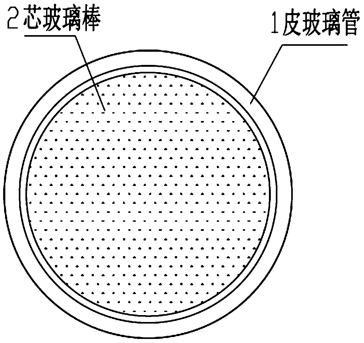
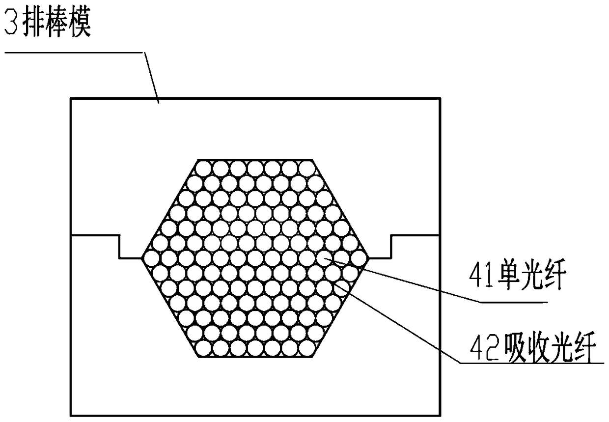
[0066] Such as figure 1 As shown, the core glass rod 1 is inserted into the skin glass tube 2, and the two are combined concentrically, and then hung on the wire drawing equipment, the skin glass tube is pumped, and the temperature of the wire drawing furnace is started to rise to the softening temperature of the glass 770~800 ℃ (the temperature can be adjusted appropriately according to the softening condition of the fiber in the drawing furnace and the actual drawing process), the glass softens and sags, and then is pulled and stretched by the drawing wheel, and the skin glass tube and the core glass rod will be bonded together, and passed through the cutting of the drawing machine When the fiber device is used, the optical fiber is cut into equal-length single fibers to form corresponding single fiber filaments 41 (such as figure 2 shown), the...

Embodiment 2

[0083] Embodiment 2: A method of making an optical fiber panel

[0084] 1) Drawing of single optical fiber

[0085] A core glass rod is inserted into the skin glass tube for concentric combination, and the rod-tube assembly is drawn into a single optical fiber; the drawing temperature is 770-800°C; the core glass rod is a glass rod with a refractive index of 1.65-1.80; the said The leather glass tube is a glass tube with a refractive index of 1.45~1.60.

[0086] 2) Drawing of stray light absorbing filament

[0087] The stray light absorbing glass is drawn into the stray light absorbing filament, and the drawing temperature is 750~780°C; the size of the stray light absorbing filament is determined according to the size of the single fiber, and is used to insert into the gap between the single fiber and the single fiber;

[0088] 3) Drawing of composite optical fiber

[0089] Arrange the drawn single optical fibers tightly into the regular hexagonal cavity of the row of rods,...

Embodiment 3

[0096] Embodiment 3: A method of making an optical fiber panel

[0097] 1) Drawing of single optical fiber

[0098] A core glass rod is inserted into the skin glass tube for concentric combination, and the rod-tube assembly is drawn into a single optical fiber; the drawing temperature is 770-800°C; the core glass rod is a glass rod with a refractive index of 1.65-1.80; the said The leather glass tube is a glass tube with a refractive index of 1.45~1.60.

[0099] 2) Drawing of stray light absorbing filament

[0100] The stray light absorbing glass is drawn into the stray light absorbing filament, and the drawing temperature is 750~780°C; the size of the stray light absorbing filament is determined according to the size of the single fiber, and is used to insert into the gap between the single fiber and the single fiber;

[0101] 3) Drawing of composite optical fiber

[0102] Arrange the drawn single optical fibers tightly into the regular hexagonal cavity of the row of rods,...


PUM

PropertyMeasurementUnit
refractive indexaaaaaaaaaa

Abstract

The invention discloses a manufacturing method of fingerprint acquisition optical fiber panel. The method comprises the steps of: inserting a core glass rod into a sheath glass tube for combination, and drawing the combination into a single optical fiber wire; drawing stray light absorption glass into a stray light absorption wire; arranging the single optical fiber wires into a cavity of a bar die, and inserting stray light absorption wires into the single optical fiber wires so as to form a composite bar; carrying out drawing to form a composite optical fiber; arranging the composite optical fibers once again into the bar die to form a secondary composite wire bar, and carrying out drawing to form an optical fiber panel blank bar; and rising the temperature of the optical fiber panel blank bar from a room temperature to about 600 DEG C for about 6 hours, maintaining the temperature for about 6 hours, then decreasing the temperature to about 30 DEG C for about 60 hours, then carrying out cutting to form the panel, and finally carrying out forming machining and fine machining. According to the invention, the material cost is low, the arranging and melting press processes are not needed, the production technology is simplified, the machining period is shortened, a large number of melting press dies, melting press furnaces and melting press equipment are not needed, the cost is substantially lowered, and the market competition demand of a fingerprint identification system is met.

Description

technical field [0001] The invention relates to the technical field of optical fiber panel production, in particular to a method for fabricating an optical fiber panel for fingerprint collection. Background technique [0002] The optical fiber panel is a hard optical fiber component composed of many closely arranged optical fibers. It has the characteristics of good light collection performance, high resolution, zero optical thickness, and can transmit high-definition images without distortion. , Widely used in input and output ports of various electronic optical devices. [0003] At present, the optical fiber panel has been used as a key component of some optical fingerprint recognition systems, which has the characteristics of small size and high recognition rate, and has gradually risen in the market. [0004] Existing fiber optic panel products are mainly used in high-end fields such as microscopic night vision, physical research, and medical treatment. They have high r...

Claims


Application Information

Patent Timeline
Patent Type & Authority Patents(China)
IPC IPC(8): G02B6/08C03B37/028
CPCC03B37/028G02B6/08
Inventor 黄朋罗新华李建杰骆志财冀海亮王斌任晓娇
Owner GUANGZHOU HONSUN OPTOELECTRONICS
Features
  • Generate Ideas
  • Intellectual Property
  • Life Sciences
  • Materials
  • Tech Scout
  • Unparalleled Data Quality
  • Higher Quality Content
  • 60% Fewer Hallucinations
Learn More