Flat high-voltage transformer and manufacturing method thereof

A technology for high-voltage transformers and flat plates, which is applied in the manufacture of transformers, fixed transformers, inductors/transformers/magnets, etc. It can solve the problems of printed circuit board chemical corrosion process, poor anti-seismic performance, high production cost, etc., and achieve easy assembly and environmental protection performance Good, high production efficiency effect

Inactive Publication Date: 2016-01-20
成都市亚丰电子技术有限责任公司
View PDF8 Cites 4 Cited by
  • Summary
  • Abstract
  • Description
  • Claims
  • Application Information

AI Technical Summary

Problems solved by technology

Flat high-voltage transformers can basically meet the above conditions. At present, most flat high-voltage transformers are composed of iron cores and cross-stacked multi-layer printed circuit boards. However, due to the long cycle of printed circuit board design, development, and debugging, this The production cost of similar flat-panel high-voltage transformers is relatively high; printed circuit boards have chemical corrosion process, which is not conducive to environmental protection; and flat-panel high-voltage transformers composed of printed circuit boards have poor anti-seismic performance due to their special structure during operation. Glue processing is required

Method used


Image

  • Flat high-voltage transformer and manufacturing method thereof
  • Flat high-voltage transformer and manufacturing method thereof
  • Flat high-voltage transformer and manufacturing method thereof

Examples


Embodiment 1

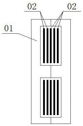
[0043] Such as Figure 1 to Figure 5 As shown, a flat high-voltage transformer includes a magnetic core 1 and a winding 2. The winding 2 includes at least two primary windings 21 and a plurality of secondary windings 22. The number of primary windings 21 and secondary windings 22 can be determined according to design requirements. . The primary winding 21 is made of electromagnetic wire, or when a large primary current is required, the primary winding 21 can be wound with copper tape or other materials, and the secondary winding 22 is made of electromagnetic wire, and the electromagnetic wire can be Wire covered wire, enameled wire, triple insulated wire, etc. The aforementioned background technology has been introduced. In the existing planar high-voltage transformer, the multilayer printed circuit board 02 is formed by stacking the primary winding and the secondary winding. In this embodiment, the primary winding 21 and the secondary winding 22 are opposite to each other. ...

Embodiment 2

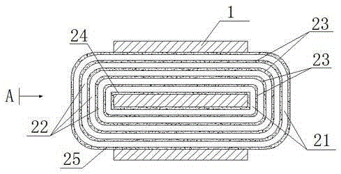
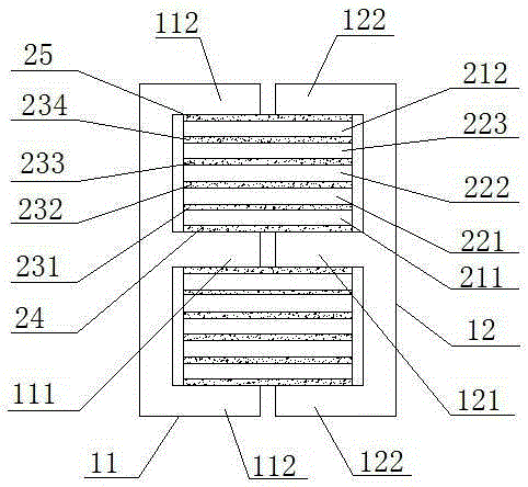
[0046] Such as Figure 2 to Figure 5 As shown, this embodiment is a further optimization of Embodiment 1, which is a three-output planar high-voltage transformer. In this embodiment, the winding 2 includes two primary windings 21 and three secondary windings 22, the inner side and the outer side of the winding 2 are primary windings 21, the two primary windings 21 are connected in parallel, and the three secondary windings 22 are located at two Intergroup insulation 23 is provided between each primary winding 21, between adjacent primary windings 21 and secondary windings 22, and between adjacent secondary windings 22. The magnetic core 1 includes a first magnetic core 11 and a second magnetic core 12, the first magnetic core 11 and the second magnetic core 12 are both "E" type magnetic cores, and the center of the first magnetic core 11 is provided with a A column 111, a first side plate 112 is provided on the opposite sides of the first magnetic core 11, a second core colum...

Embodiment 3

[0049] Such as Figure 4 to Figure 6 As shown, the difference between this embodiment and embodiment 2 is that the first magnetic core 11 selects an "E" type magnetic core, the second magnetic core 12 selects an "I" type magnetic core, and the first magnetic core 11 and the second The magnetic cores 12 are combined into a "day" shape, and the winding 2 is located in the "E"-shaped winding space of the first magnetic core 11 . In this embodiment, the cross-section of the planar high-voltage transformer includes in order from inside to outside: first magnetic core center column 111, bottom layer insulation 24, primary winding 21, intergroup insulation 23, secondary winding 22, intergroup insulation 23, secondary The primary winding 22 , the intergroup insulation 23 , the secondary winding 22 , the intergroup insulation 23 , the primary winding 21 , the outer layer insulation 25 , and the first side plate 112 . Compared with Embodiment 2, the second magnetic core 12 in this embo...


PUM


Abstract

The invention discloses a flat high-voltage transformer, which comprises a magnetic core and a winding, wherein the winding comprises at least two primary windings and a plurality of secondary windings; each primary winding is wound by an electromagnetic wire or a copper strip; each secondary winding is wound by the electromagnetic wire; the primary windings and the secondary windings are sequentially arranged in a ring relative to the center of the magnetic core from the inside to the outside; and interblock insulators are arranged between the adjacent primary windings and secondary windings and between the adjacent secondary windings. According to the flat high-voltage transformer, when various performance requirements of the flat high-voltage transformer are met, the development period is shortened; the manufacturing cost is reduced; and the flat high-voltage transformer is relatively environment-friendly. The invention further discloses a manufacturing method of the flat high-voltage transformer. The manufacturing method comprises the following steps: wrapping a bottom insulator; winding the primary windings and wrapping the interblock insulators; winding the secondary windings and wrapping the interblock insulators; repeating the steps for N times; winding the primary windings and wrapping an outer insulator; assembling the windings, the magnetic core and a housing; and filling a potting compound. The flat high-voltage transformer is simple in procedure and high in manufacturing efficiency; and the process is relatively easy to control.

Description

technical field [0001] The invention relates to the technical field of power electronics, in particular to a flat high-voltage transformer and a manufacturing method thereof. Background technique [0002] With the rapid development of national defense in our country, the miniaturization of weapons and equipment is listed as a key requirement in the field of aerospace electronic warfare and communications. [0003] The radar traveling wave tube power supply in this field is an important part of the entire system, and the high-voltage transformer is the core device that provides traveling wave tube energy in the entire power system. The transformer is required to meet the requirements of high efficiency, small size, ultra-thin, good coupling, and distribution Small capacitance, small leakage inductance, high dielectric strength, high and low temperature resistance, low air pressure and other technical conditions. Flat high-voltage transformers can basically meet the above con...

Claims


Application Information

Patent Timeline
Patent Type & Authority Applications(China)
IPC IPC(8): H01F30/06H01F27/30H01F27/24H01F27/32H01F41/00H01F41/06H01F41/12
Inventor 唐学全唐世泽
Owner 成都市亚丰电子技术有限责任公司
Why Eureka
Try Eureka