One-piece flange automatic welding equipment with central through hole

A central through-hole, integrated technology, applied in welding equipment, welding equipment, arc welding equipment, etc., can solve the problems of low production efficiency, increase the labor intensity of operators, and difficult to ensure welding quality, and achieve a high degree of welding automation. , The welding quality is stable and reliable, and the welding quality is easy to ensure the effect

Active Publication Date: 2017-09-29
JINAN JINLUDING WELDING TECH CO LTD
View PDF7 Cites 0 Cited by
  • Summary
  • Abstract
  • Description
  • Claims
  • Application Information

AI Technical Summary

Problems solved by technology

After the whole weld seam is welded, it is necessary to turn off the welding power supply first, and then turn off the positioner; because in the welding equipment of the prior art, the positioner part, the welding power source and the welding torch part are two relatively independent systems, When there are multiple welds, it is necessary to constantly change the relative position of the welding cross arm and the positioner, and repeat the steps of adjusting the position of the welding cross arm, turning on the positioner, turning on the power, and welding to complete the welding of all welds on the workpiece. Welding, low welding efficiency
Moreover, closed-loop control cannot be realized, the operation is cumbersome, the repeatability is poor, the labor intensity of welding operators is high, the production efficiency is low, and the welding quality is not easy to control
In addition, since the welding torch is fixed at a certain position above the weld seam, the welding torch cannot automatically swing and move up and down during the welding process. When welding parts with groove requirements, it needs to be manually adjusted in real time to make the welding torch swing left and right; especially when When the pipe fittings have obvious ellipticity, it is necessary to manually adjust the height of the welding torch in real time to realize the adjustment of the arc length and stabilize the arc, which not only increases the labor intensity of the operator, but also makes it difficult to guarantee the welding quality

Method used


Image

  • One-piece flange automatic welding equipment with central through hole
  • One-piece flange automatic welding equipment with central through hole
  • One-piece flange automatic welding equipment with central through hole

Examples


Embodiment Construction

[0040] In order to clearly illustrate the technical features of the present invention, the present invention will be further described below through specific implementation modes and in conjunction with the accompanying drawings.

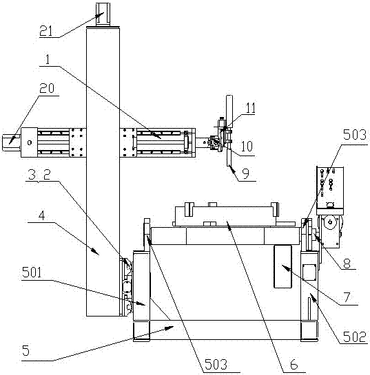
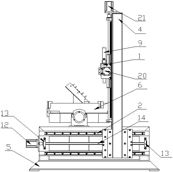
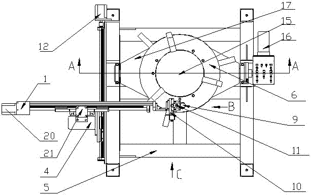
[0041] see Figure 1 to Figure 3 , an integrated flange automatic welding equipment with a central through hole, including a control system, a welding cross arm, a welding torch 9 and a positioner, the positioner includes a base 5, and is connected to the base 5 through a rotating shaft 8 of the machine head The machine head and the displacement motor 16, the displacement motor 16 drives the rotation of the machine head rotary shaft 8 to make the machine head displace, the machine head includes a flip frame 17, a main motor 7, a welding chuck 6 for fixing workpieces, 6 is connected with the main motor 7 through a rotary device; the base 5 is provided with a left bracket 501 and a right bracket 502, and the upper parts of the left bracket 501 and the...


PUM


Abstract

The invention discloses an integral flange automatic welding device with a central through hole. The welding cross arm is slidably connected to the base of the positioner, and can move forward and backward relative to the base; the welding chuck is connected to the main motor through the rotary support fixed on the turning frame; the turning frame has a central through hole, and the workpiece can pass through the center through the hole The welding chuck can hold any part of the workpiece, so that the positioner, welding power supply and welding torch can be integrated structure, not only suitable for long pipe welding, but also when there are multiple welds on the workpiece, no need Repeatedly changing the relative position of the welding cross arm and the positioner can complete the welding of all welds on the workpiece. The welding cross arm is equipped with a welding oscillator and an arc length regulator. The welding torch is installed on the arc length regulator, which can automatically realize the swing and up and down adjustment, and is suitable for weldments with groove requirements and workpieces with obvious ellipticity. Welding, without human adjustment or intervention, realizes closed-loop control, and the welding quality is easy to guarantee.

Description

technical field [0001] The invention relates to the technical field of welding equipment, in particular to an automatic welding equipment for pipes and flanges. Background technique [0002] Pipeline welding equipment generally consists of a positioner, a welding power source, and a welding torch. The positioner includes a base, a displacement motor, and a machine head connected to the base through the rotation shaft of the machine head. The pinion at the shaft end of the positioner motor is driven and fixed on the machine. The large gear on the rotary shaft of the head displaces the machine head. The machine head includes a flip frame, a main motor, a rotary shaft, and a welding chuck. The welding chuck is connected to the end of the rotary shaft, and the rotary shaft and welding chuck are driven by the main motor. Rotate, and then drive the workpiece to rotate. Since the welding fixture of the positioner can only hold the end of the workpiece, when welding a workpiece whos...

Claims


Application Information

Patent Timeline
Patent Type & Authority Patents(China)
IPC IPC(8): B23K9/022B23K37/047B23K37/02B23K9/28
CPCB23K9/022B23K9/287B23K37/0229B23K37/0252B23K37/047
Inventor 刘彬隋仲涛
Owner JINAN JINLUDING WELDING TECH CO LTD
Why Eureka
Try Eureka