A plowing type PDC drill bit suitable for hard formations

A technology for hard formations and drill bits, which is applied to drill bits, drilling equipment, earthwork drilling and production, etc. It can solve the problems of short life of drill bits and low drilling efficiency, and achieve the effects of reducing rock strength, rapid drilling, and destroying internal stress

Inactive Publication Date: 2016-01-27
CHINA PETROCHEMICAL CORP +2
View PDF9 Cites 9 Cited by
  • Summary
  • Abstract
  • Description
  • Claims
  • Application Information

AI Technical Summary

Problems solved by technology

[0003] The purpose of the present invention is to provide a plow cutting PDC drill bit suitable for hard formations, which can effectively solve the problems of short drill bit life and low drilling ef...

Method used


Image

  • A plowing type PDC drill bit suitable for hard formations
  • A plowing type PDC drill bit suitable for hard formations
  • A plowing type PDC drill bit suitable for hard formations

Examples


Embodiment 1

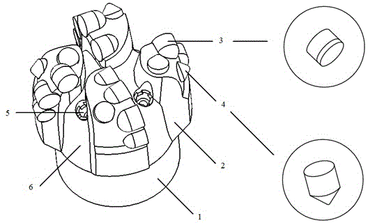
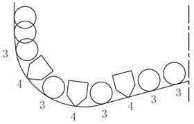
[0026] When the tapered PDC teeth 4 and the polycrystalline diamond composite sheet 3 are alternately arranged, as figure 2 As shown, the bottom hole cutting track of the conical PDC tooth 4 is located between the bottom hole cutting tracks of adjacent polycrystalline diamond compacts 3 on the bottom hole contour line. The polycrystalline diamond composite sheet is used as the main cutting tooth of the blade, and is arranged on the blade in a backward tilt manner, and the backward tilt angle of the composite sheet ranges from 7 degrees to 13 degrees. The conical PDC teeth are used as the rear row of teeth of the blade, and are arranged on the blade in a forward-inclination manner. The forward inclination angle of the conical teeth ranges from 13 degrees to 18 degrees. When the tapered PDC teeth and the polycrystalline diamond composite sheet are arranged in a staggered manner, the cutting edge heights of the two are the same.

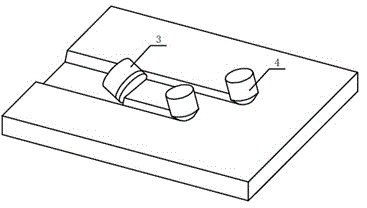
[0027] Such as image 3 As shown, during the d...

Embodiment 2

[0029] When the tapered PDC teeth 4 are arranged in the same track as the polycrystalline diamond composite sheet 3, as Figure 4 As shown, the bottom-hole cutting trajectory of the conical PDC cutter 4 is the same as the bottom-hole cutting trajectory of one of the polycrystalline diamond compacts 3 on the bottom-hole contour line. The polycrystalline diamond composite sheet is used as the main cutting tooth of the blade, and is arranged on the blade in a backward tilt manner, and the backward tilt angle of the composite sheet ranges from 7 degrees to 13 degrees. The conical PDC teeth are used as the rear row of teeth of the blade, and are arranged on the blade in a forward-inclination manner. The forward inclination angle of the conical teeth ranges from 13 degrees to 18 degrees. When the tapered PDC teeth and the polycrystalline diamond composite sheet are arranged on the same track, the cutting edge height of the tapered PDC teeth is 2 mm or less lower than that of the pol...


PUM


Abstract

The invention provides a plowing type PDC drill bit suitable for hard formations. The plowing type PDC drill bit comprises a drill bit base body, cutter blades and cutting teeth. The drill bit base body is provided with at least two cutter blades and chip grooves are formed between adjacent cutter blades. The cutter blades are provided with the cutting teeth. The cutting teeth include tapered PDC teeth and polycrystalline diamond compacts arranged on the cutter blades. The polycrystalline diamond compacts cut rocks at a rear rake angle and the tapered PDC teeth plow rocks at the positive rake angle. The tops of the tapered PDC teeth are sharp and can cut into rocks easily and form plowing furrows at well bottoms, so that the internal stress of well bottom rocks is released and the rock strength is reduced; the working surfaces of the polycrystalline diamond compacts are large, so that the rocks can be cut in large area; through the organic combination of the PDC teeth of two different structures, the rock breaking efficiency of the drill bit can be greatly improved, the problems of low hard formation drilling speed and short service life of drill bits are effectively solved, and the objectives of increasing the drilling efficiency, shortening the drilling period and reducing the drilling cost are achieved.

Description

technical field [0001] The invention relates to a drill bit for oil and gas well drilling, in particular to a plow cutting PDC drill bit suitable for hard formations. Background technique [0002] As a high-efficiency rock-breaking tool, the PDC bit has been more and more widely used in oil and gas drilling. It has fast drilling speed and high footage in soft to medium hard formations. However, in deep wells and oil and gas drilling under complex geological conditions, difficult-to-drill formations such as carbonate rocks, igneous rocks, and metamorphic rocks are often drilled, which have high strength, high hardness, poor drillability, and strong abrasiveness. The conventional PDC bit is used to drill the above-mentioned strata, and the wear speed of the PDC cutting teeth is relatively fast, resulting in slow ROP, low drilling footage, short life, long drilling cycle and high cost. Therefore, it is necessary to design a PDC drill bit specially used for hard formation drill...

Claims


Application Information

Patent Timeline
IPC IPC(8): E21B10/43E21B10/54
Inventor 刘天科刘成贵裴建忠刘湘华路峰邹德永李海涛黄勇李文明赵永斌
Owner CHINA PETROCHEMICAL CORP
Why Eureka
Try Eureka