Large view field angle eyepiece optical system

A technology of field of view and eyepiece, which is applied in the optical field, can solve the problems of difficult design and aberration optimization, difficult production, and large lens diameter, so as to achieve a high immersive visual experience, reduce manufacturing costs, and reduce system aberrations. Eliminate the effect

Active Publication Date: 2016-01-27
SHENZHEN NED OPTICS CO LTD
View PDF9 Cites 32 Cited by
  • Summary
  • Abstract
  • Description
  • Claims
  • Application Information

AI Technical Summary

Problems solved by technology

[0004] Patent Document 1 (Chinese Patent Publication No. CN101609208A) provides an eyepiece system for head-mounted displays. The field of view of the eyepiece system is not large enough, not exceeding 55 degrees, and cannot meet the application of virtual reality; the lens size of the optical system Large size will lead to a large head-mounted near-eye display; insufficient consideration of mass production, insufficient space reserved for assembly at the edge of the lens, resulting in difficult assembly of the lens and difficult production
Patent Document 2 (Chinese Patent Publication No. CN101887166A) provides an eyepiece system for a head-mounted display. The field of view of the e

Method used


Image

  • Large view field angle eyepiece optical system
  • Large view field angle eyepiece optical system
  • Large view field angle eyepiece optical system

Examples


Embodiment Construction

[0059] The present invention will be further described below in conjunction with the accompanying drawings and specific embodiments.

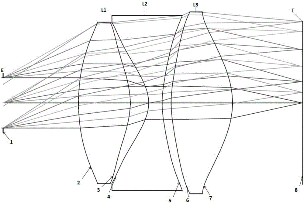
[0060] as attached figure 1 As shown, the optical system diagram of the eyepiece of the first embodiment of the present invention, from the human eye observation side to the display device I side (from left to right), is successively the diaphragm E, the first lens L1, the second lens L2, the first lens L Three lenses L3 and a display device I. In the present invention, the diaphragm E can be the exit pupil of the eyepiece optical system, which is a virtual light exit aperture. When the pupil of the human eye is at the diaphragm position, the best imaging effect can be observed. In this embodiment, the first lens L1 and the third lens L3 are positive lenses, the second lens L2 is a negative lens, and the surface of the second lens toward the human eye observation side is concave toward the human eye observation side, and the radius of curvatur...


PUM


Abstract

The invention provides a large view field angle eyepiece optical system for a head-mounted displayer, wherein the large view field angle eyepiece optical system comprises a first lens, a second lens, and a third lens which are successively and coaxially arranged along an optical axis direction from a human eye observing side to a displayer side; the first lens and the third lens are all positive lenses and the second lens is a negative lens; the surface, facing the human eye observing side, of the first lens is projected towards the human eye observing side and has a positive curvature radius; the surface, facing a diaphragm side, of the second lens is projected away from the human eye observing side and has a negative curvature radius; and at the same time, the materials, the focuses and the positions of the first lens, the second lens and the third lens should satisfy certain relationship, so that an image displayed on the displayer is imaged in human eyes after the image is amplified by an eyepiece. The eyepiece has the advantages of large hole diameter, large view field, high resolution ratio, low distortion and small size; and the eyepiece is suitable for head-mounted displayers and apparatuses similar to the head-mounted displayers.

Description

technical field [0001] The invention relates to the field of optical technology, in particular to an eyepiece optical system suitable for head-mounted displays or similar devices. Background technique [0002] With the continuous development of electronic devices towards ultra-miniaturization, as well as the development of new computer, microelectronics, optoelectronic devices and communication theories and technologies, wearable computing, a new model based on "people-oriented" and "integration of man and machine" has become possible. . Applications are emerging in military, industrial, medical, education, consumer and other fields. In a typical wearable computing system architecture, the head-mounted display device is a key component. The head-mounted display device guides the video image light emitted by the micro-image display (such as transmissive or reflective liquid crystal display, organic electroluminescent device, DMD device) to the user's pupil through optical t...

Claims


Application Information

Patent Timeline
IPC IPC(8): G02B27/01G02B25/00
CPCG02B25/001G02B27/0172
Inventor 曹鸿鹏彭华军
Owner SHENZHEN NED OPTICS CO LTD
Why Eureka
Try Eureka