Negative pressure phase change power generation system and steam turbine power generation device

A power generation system and phase change technology, applied in geothermal energy systems, machines/engines, mechanisms for generating mechanical power, etc., can solve the problems of high energy consumption of power generation devices, limited power generation, unfavorable environmental protection, etc., and achieve low cost input, Improve utilization rate and make easy effects

Active Publication Date: 2018-05-08
LANZHOU JINFULE BIOTECH CO LTD +3
View PDF5 Cites 0 Cited by
  • Summary
  • Abstract
  • Description
  • Claims
  • Application Information

AI Technical Summary

Problems solved by technology

[0005] The purpose of the present invention is to solve the defects of the existing power generation devic...

Method used


Image

  • Negative pressure phase change power generation system and steam turbine power generation device
  • Negative pressure phase change power generation system and steam turbine power generation device
  • Negative pressure phase change power generation system and steam turbine power generation device

Examples


Embodiment 1

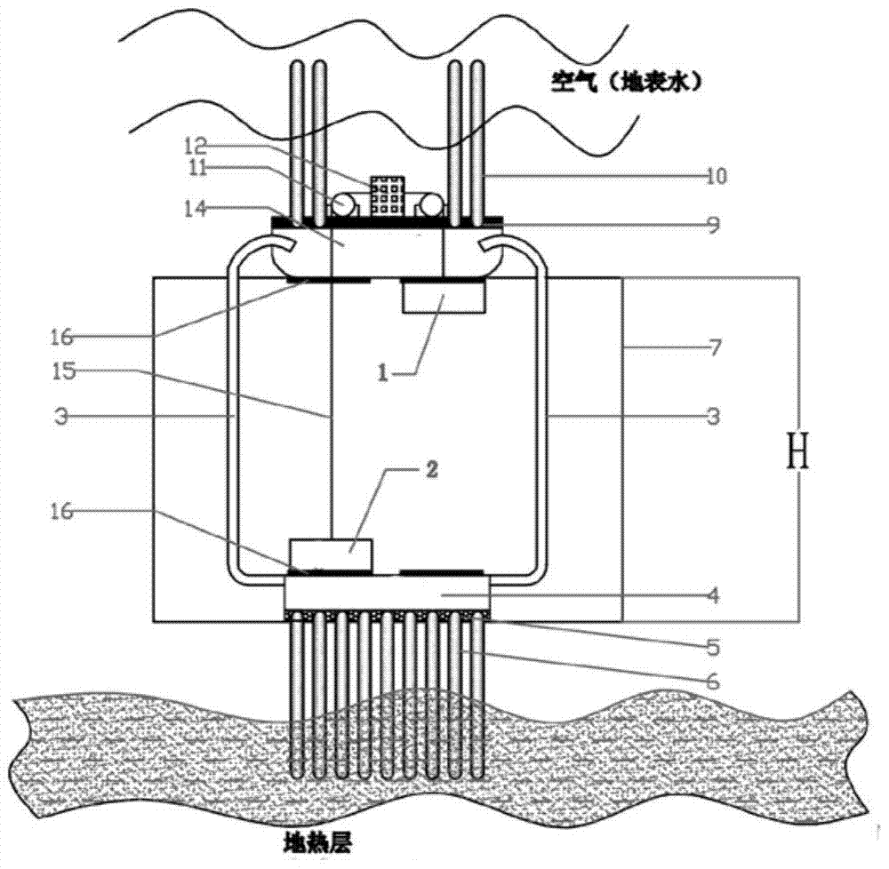
[0034] Such as figure 1 As shown, the low-temperature negative pressure phase-change power generation device of the embodiment of the present invention includes a first power generation box, a second power generation box, a gas delivery pipeline 3, and a heating room (the liquid in the power generation box is put into it, and then liquefied device) 4, heating plate 5, heating superconducting heat pipe 6, fixing and stabilizing device of the whole device 7, heat dissipation plate 9, heat dissipation superconducting heat pipe 10, power generation box guiding device 11, generator set 12, condensation room 14, power generation Box movement connecting device 15, liquid filling valve 16.

[0035] The heating plate 5 is connected with the heat dissipation end of the heating superconducting heat pipe 6, so that the heat conduction is more uniform and rapid. The heat dissipation plate 9 is made of high thermal conductivity material, and the heat dissipation plate 9 is connected with t...

Embodiment 2

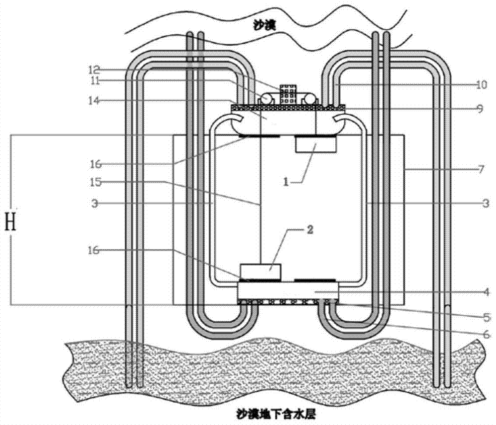
[0044] Such as figure 2 As shown, the difference between this embodiment and the above-mentioned embodiments is that the structure of the heating superconducting heat pipe 6 and the heat dissipation superconducting heat pipe 10 are somewhat different. figure 2 The heating superconducting heat pipe 6 draws heat energy from the top high-temperature heat source of the fixing and stabilizing device 7 of the whole device, and then transfers the heat energy to the heating room 4 by heating the superconducting heat pipe 6, and converts the gaseous medium in the condensation room into The heat energy released during the process of liquid medium is transferred to the bottom low-temperature heat source of the fixing and stabilizing device 7 of the whole device through the heat dissipation superconducting heat pipe 10, thereby completing the process of phase change power generation and generating electric energy.

[0045] figure 2 It is suitable for the condition that the bottom of t...

Embodiment 3

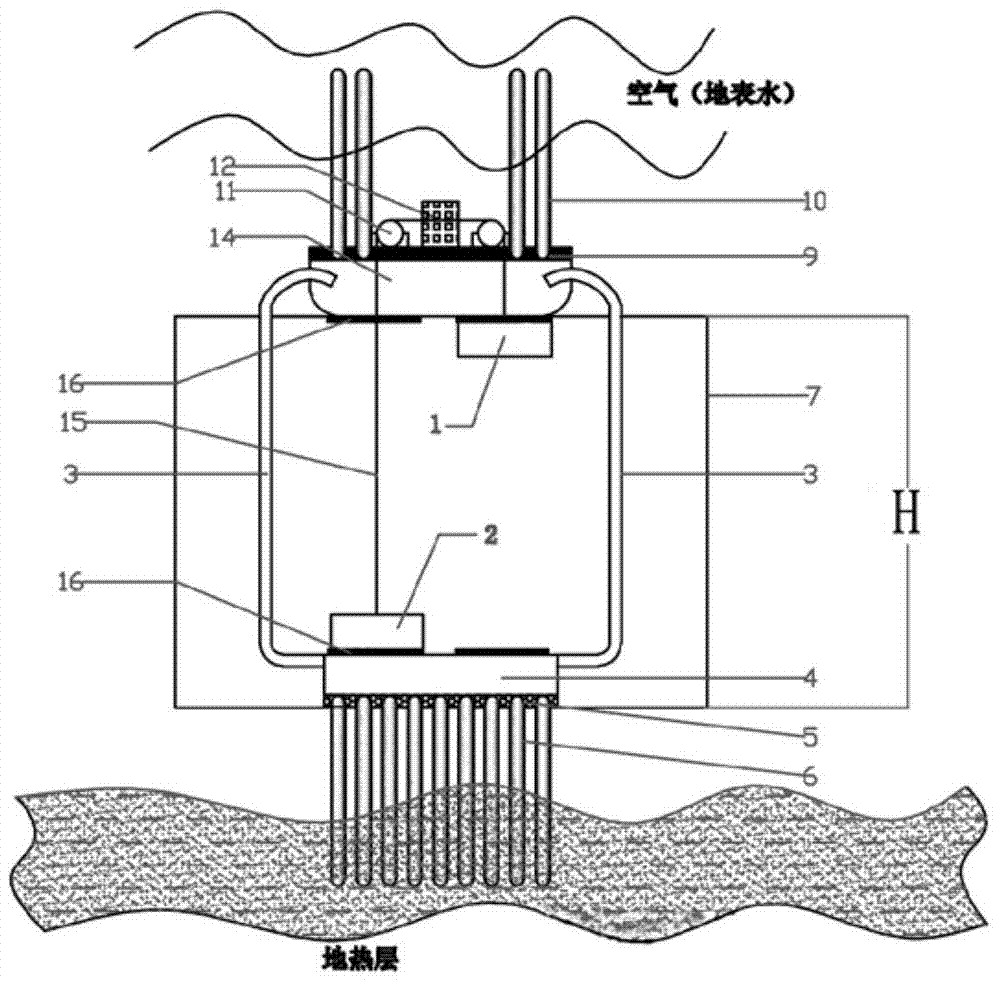
[0047] Such as image 3 as shown, image 3 structure with figure 1 The structures are the same, except that the heating room 4, the gas delivery pipeline 3, the condensation room 14, the first power generation box 1, the second power generation box 2 and the second power generation box 2 etc. will select materials that can withstand high temperature and high pressure. For example, the high-temperature underground geothermal energy is used as a high-temperature heat source, and the air and surface water on the ground are used as a low-temperature heat source.

[0048] image 3 The selected high-temperature heat source is higher than 100°C, and the pressure generated is greater than normal atmospheric pressure.


PUM


Abstract

The invention relates to the technical field of power generation equipment, in particular to a negative pressure phase change power generation system and a steam turbine power generation device. The system includes a heating superconducting heat pipe, a heat dissipation superconducting heat pipe, a heating room, a condensation room and a gas delivery pipeline; there is a height difference between the heating room and the condensation room and is connected through a gas delivery pipeline; the heat absorption end of the heating superconducting heat pipe and the The heat source is connected, the heat dissipation end of the heating superconducting heat pipe is connected with the heating plate, and the heating room is equipped with a thermal liquid medium. The heat dissipation end of the heat pipe is connected with a low-temperature heat source. The invention introduces the earth's natural energy into recombined phase-change power generation through heat pipes or superconductors, effectively replaces conventional energy sources such as coal and nuclear energy, maximizes the use of infinite natural resources, and improves the utilization rate of natural resources. The power generation system has simple equipment, low cost input, easy manufacture and no pollution.

Description

technical field [0001] The invention relates to the technical field of phase change power generation, in particular to a negative pressure phase change power generation system and a steam turbine power generation device. Background technique [0002] With the continuous development of science and technology, the demand for energy in all walks of life is becoming increasingly urgent. At present, most power generation systems are still using relatively traditional methods such as coal to generate power. On the one hand, coal resources are limited and cannot meet the needs of high-power power generation. On the other hand, the use of coal for power generation increases the pollution and damage to the natural environment. , is not conducive to environmental protection. [0003] In recent years, the use of wind energy, hydropower, solar energy, nuclear energy and other power generation technologies has been gradually developed, but these power generation technologies consume a l...

Claims


Application Information

Patent Timeline
IPC IPC(8): F03G7/00F03G4/00
CPCF03G7/04
Inventor 金季藩
Owner LANZHOU JINFULE BIOTECH CO LTD
Why Eureka
Try Eureka