Evaporating pipe

An evaporative tube and main tube technology, applied in the field of evaporative heat transfer tubes and heat transfer equipment, can solve the problem that the requirements of refrigeration equipment for the heat exchange performance of evaporators cannot be fully met, the improvement of heat exchange efficiency of heat transfer tubes is limited, and the reduction of pipe material The utilization rate of heat dissipation area and other issues can improve the heat exchange rate, increase the surface area, and increase the contact area.

Inactive Publication Date: 2016-02-03
GOLDEN DRAGON PRECISE COPPER TUBE GROUP
View PDF6 Cites 4 Cited by
  • Summary
  • Abstract
  • Description
  • Claims
  • Application Information

AI Technical Summary

Problems solved by technology

[0004] 1. Although it can improve the heat transfer performance of the evaporating side to a certain extent, due to the uniform fin height, uniform fin spacing, and uniform distribution, it cannot make full use of the surface tension of the droplets to improve the heat transfer performance. The improvement of the heat transfer efficiency of the heat pipe is limited, and cannot fully meet the requirements of the refrigeration equipment for the heat transfer performance of the evaporator;
[0005] 2. Although the fins are beneficial to withstand pressure changes because of the circumferential inclined surface with trapezoidal cross-section, this cross-sectional shape also makes it difficult for liquid droplets to spread and thin evenly on the surface of the inclined trapezoidal tube, thus failing to make full use of the surface area A heat exchange liquid film is formed, whereby the increase in the heat exchange rate of the tube is limited
[0006] 3. It increases the heat transfer area by adding fins on the outer surface of the heat transfer tube to increase the heat transfer efficiency, but it is easy to accumulate refrigerant between the fins used in the falling film evaporation heat transfer tube to form a meniscus, which is not easy Facilitate the flow and drip of refrigerant
[0007] In addition, the existing enhanced heat transfer tubes have been used for many years, and some of the tubes only change in the number and height of the fins. Incomplete fins reduce the utilization rate of the heat dissipation area of ​​the tube; and although some of the tubes use the irregular shape of the fins such as bending or zigzag and their staggered arrangement to enhance heat transfer, the processing technology is relatively complicated

Method used


Image

  • Evaporating pipe
  • Evaporating pipe

Examples


Embodiment Construction

[0023] In order to make the above objects, features and advantages of the present invention more obvious, the technical contents of the preferred embodiments of the present invention will be described in detail below in conjunction with the accompanying drawings.

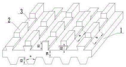
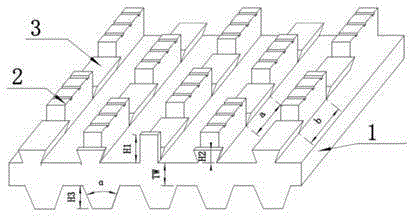
[0024] figure 1 It is an axonometric view of the first embodiment of the heat transfer enhanced evaporation tube of the present invention. As shown in the figure, the enhanced heat transfer evaporating tube of the present invention includes: a main tube 1 and fins 2 integrally formed with the main tube, and the fins 2 are arranged on the outer surface of the main tube in a manner of spirally coiling around the axis of the main tube , the fins include main fins 2 and auxiliary fins 3 that are continuously staggered along the length direction, wherein the height of the main fins 2 is greater than the height of the auxiliary fins 3; wherein, the main fins 2 and the axially adjacent The secondary fins 3 are adjoined or...


PUM


Abstract

The invention relates to an evaporating pipe. The evaporating pipe comprises a main body pipe and a fin integrally molded with the main body pipe, wherein the fin is arranged on the outer surface of the main body pipe in a manner of being coiled around the axis of the main body pipe into helical angles, the fin comprises a plurality of main fins and auxiliary fins, which are continuously distributed in the length direction in a crossed manner, and the main fins are higher than the auxiliary fins. The main fins and the circumferential adjacent auxiliary fins are distributed in a circumferential butt joint and high-low staggered manner, the main fins are in a shape of a rectangular longitudinal cross section parallel to the axis of the pipe, and the auxiliary fins are in a shape of an inverted trapezoidal cross section parallel to the axis of the pipe. The evaporating pipe is suitable for the sprinkling evaporation heat transferring mode of an absorption type unit. The pipe fin structure can promote water drops falling on the outer wall of the pipe to rapidly spread at helical angles with the axis and in the circumference, so that the thickness of a liquid film is reduced, heat transferring resistance is reduced, and evaporation heat exchange efficiency is improved.

Description

technical field [0001] The invention relates to the technical field of heat transfer equipment, in particular to the technical field of evaporation heat transfer tubes, and more particularly to an evaporation heat transfer tube used to enhance the heat exchange performance of an evaporator in an absorption unit. Background technique [0002] Since June 1990 in London, England, it was confirmed that the timetable for restricting the use of CFC (Cholrofluorocarbons, Freon) was advanced. Developed countries are not allowed to use it before 2000, and developing countries can extend it for another 10 years. The research and application of non-CFC substitutes are rapid. With the development, green and environment-friendly CFC-free refrigeration units have gradually been widely used, and lithium bromide absorption refrigerators are one of them. With the advancement of science and technology, the continuous innovation of new technologies and new methods has made lithium bromide re...

Claims


Application Information

Patent Timeline
Patent Type & Authority Applications(China)
IPC IPC(8): F28F1/36
Inventor 常建民武永强李彭滑兆成李前方唐永立
Owner GOLDEN DRAGON PRECISE COPPER TUBE GROUP
Why Eureka
Try Eureka