Fluorescence intensity ratio temperature measurement method based on fluorescence spectral line broadening mechanism

A fluorescence intensity ratio and fluorescence spectrum line technology, applied in the field of fluorescence intensity ratio temperature measurement, can solve the problems of low temperature measurement sensitivity and temperature measurement accuracy

Inactive Publication Date: 2016-02-03
HARBIN INST OF TECH
View PDF3 Cites 18 Cited by
  • Summary
  • Abstract
  • Description
  • Claims
  • Application Information

AI Technical Summary

Problems solved by technology

[0006] The present invention aims to solve the problem of low temperature measurement sensitivity and temperature measurement accuracy of the existing temperatur

Method used


Image

  • Fluorescence intensity ratio temperature measurement method based on fluorescence spectral line broadening mechanism
  • Fluorescence intensity ratio temperature measurement method based on fluorescence spectral line broadening mechanism
  • Fluorescence intensity ratio temperature measurement method based on fluorescence spectral line broadening mechanism

Examples


specific Embodiment approach 1

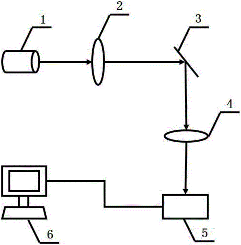
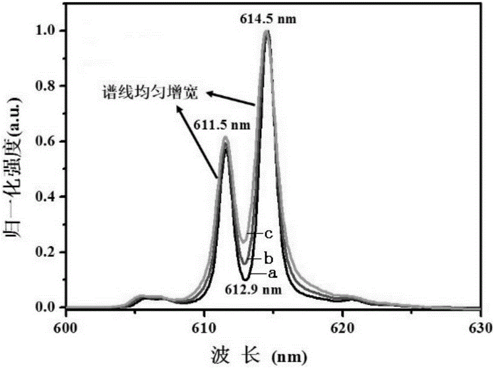
[0014] Specific Embodiment 1: In this embodiment, a fluorescence intensity ratio temperature measurement method based on the fluorescence spectral line broadening mechanism is carried out according to the following steps: 1. The near-ultraviolet light emitted by the 405nm light-emitting diode is converged and irradiated to Eu 3+ On the doped temperature-sensitive material, Eu 3+ The fluorescence emitted by the doped temperature-sensitive material is converged into the imaging spectrometer through another convex lens; the fluorescence collected by the imaging spectrometer has two fluorescence peaks, the fluorescence peaks are 611.5nm and 614.5nm respectively, and the two fluorescence peaks overlap to form a valley; 2. Connect the imaging spectrometer to the computer, and the computer performs analysis and processing, calculates and records the variation of the fluorescence intensity ratio between the valley value and the fluorescence peak A with the calibration temperature, and ...

specific Embodiment approach 2

[0016] Specific embodiment two: the difference between this embodiment and specific embodiment one is: the Eu 3+ Doped temperature-sensitive material is Eu 3+ :CaWO 4 . Others are the same as in the first embodiment.

specific Embodiment approach 3

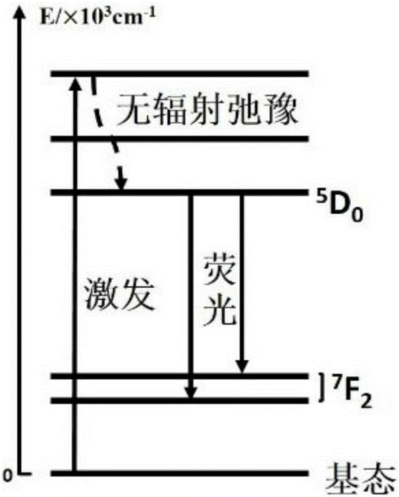
[0017] Embodiment 3: This embodiment differs from Embodiment 1 or Embodiment 2 in that: the two fluorescence peaks in step 1 both come from the same transition from one upper energy level to two adjacent lower energy levels. Others are the same as in the first or second embodiment.


PUM


Abstract

The invention discloses a fluorescence intensity ratio temperature measurement method based on fluorescence spectral line broadening mechanism. The invention solves the problems of low temperature measurement sensitivity and low temperature measurement accuracy in existing intensity ratio temperature measurement technology, and the method comprises the following steps: the near ultraviolet emitted by a 405nm LED passes through a convex lens and is gathered and irradiated on an Eu3+ doped temperature-sensitive material; the fluorescence emitted by the Eu3+ doped temperature-sensitive material is gathered through a convex lens and is incidented into an imaging spectrometer; the spectrometer is connected to a computer for data processing; a valley peak value fluorescence intensity ratio temperature curve is established; calibration is conducted; then the Eu3+ doped temperature-sensitive material is put in a temperature field to be measured; and the fluorescence emitted by the temperature-sensitive material is monitored and is compared with the valley peak value fluorescence intensity ratio temperature curve. Within a wide temperature scope, the sensitivity is appropriate; the temperature measurement scope is wide; and the temperature-sensitive material won't be replaced frequently. The method can be applied in rare earth fluorescence temperature measurement field.

Description

technical field [0001] The invention relates to a fluorescence intensity ratio temperature measurement method based on a fluorescence spectral line broadening mechanism. Background technique [0002] In order to meet the needs of temperature measurement in certain environments in scientific research and industrial production, fluorescent temperature sensing technology, a temperature measurement method based on fluorescent materials, has important application value, which can realize non-contact, long-term, stable and stable temperature measurement. Accurate temperature measurement. [0003] Fluorescence Intensity Ratio Thermometry (FIR) is the most widely used fluorescent temperature sensing technology. This method utilizes two adjacent thermally coupled energy levels of excited rare earth ions to emit when they transition to a low energy level. Using the ratio of the fluorescence intensity to measure temperature, using this ratio method to measure temperature has the advan...

Claims


Application Information

Patent Timeline
IPC IPC(8): G01K11/32
Inventor 张治国周圆秦峰赵华郑仰东
Owner HARBIN INST OF TECH
Why Eureka
Try Eureka