Missile-borne conformal microstrip antenna

A microstrip antenna and missile-borne technology, which is applied in the field of missile-borne conformal microstrip antennas, can solve the problems of affecting the electrical performance of the antenna, the deterioration of positioning time and positioning accuracy, and achieve the purpose of avoiding breakage, improving aerodynamic performance and structural reliability, The effect of improving structural reliability and ammunition aerodynamic performance

Inactive Publication Date: 2016-02-03
GUANGDONG SHENGLU TELECOMM TECH
View PDF10 Cites 8 Cited by
  • Summary
  • Abstract
  • Description
  • Claims
  • Application Information

AI Technical Summary

Problems solved by technology

[0005] The currently widely used conformal antennas on missiles are generally wound with a helical antenna on the surface of the missile or fixed on the surface of the missile in the form of a small microstrip antenna with a plastic shell. However, the use of shock-absorbing measures for missile-borne antennas and miniaturized microstrip antennas seriously affects the electrical performance of the antennas, seriously deteriorating the positioning time and positioning accuracy.

Method used


Image

  • Missile-borne conformal microstrip antenna
  • Missile-borne conformal microstrip antenna
  • Missile-borne conformal microstrip antenna

Examples


Embodiment 1

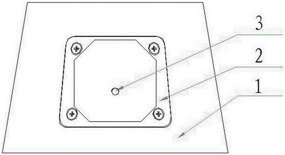
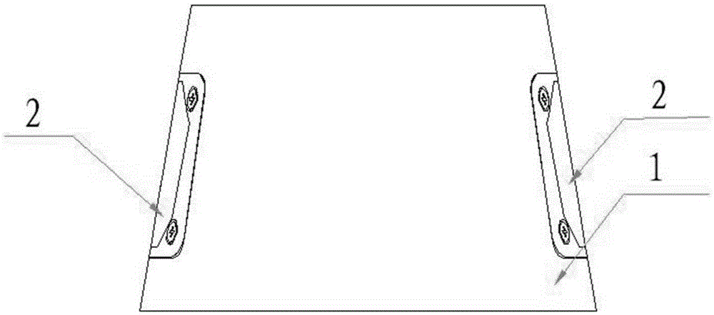
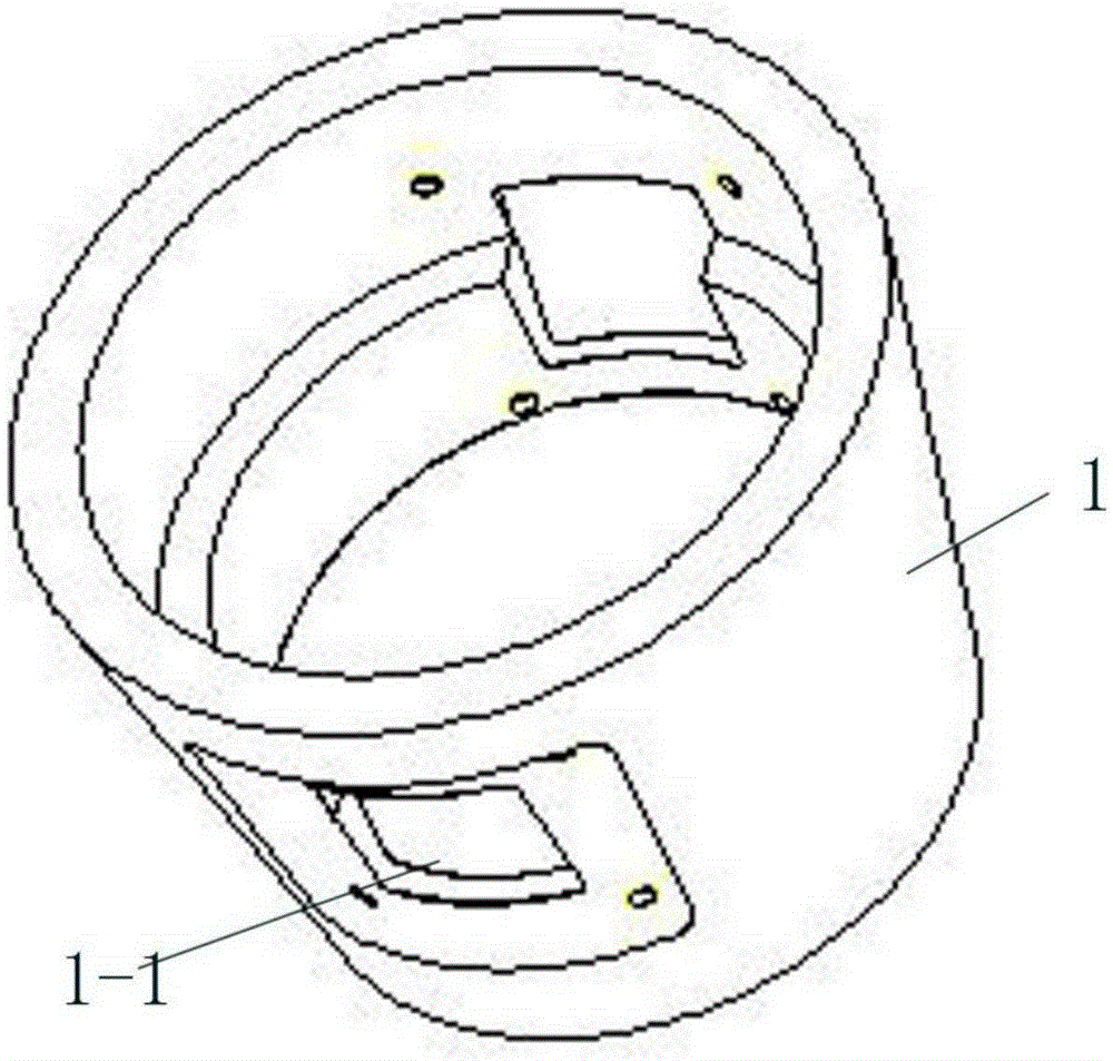
[0038] Such as Figure 1—Figure 5f As shown, the present invention is a missile-borne conformal microstrip antenna, including a first tapered cavity 1 and a first conformal microstrip antenna 2, and the inner wall of the tapered cavity is equipped with electrical devices, such as a low-noise amplifier circuit Wait. A plurality of first conformal slots 1-1 can be arrayed in the axial direction of the tapered cavity, and the conformal microstrip antenna is fixed at the bottom of the conformal slot by conductive glue bonding or screw connection; in this embodiment, the first The tapered cavity arrays 2 conformal slots along the axis, the array angle is 180°, and 4 M2 threaded through holes 1-2 are drilled at the bottom of the conformal slots to lock the conformal microstrip antenna. Electrical devices, such as low noise amplifier circuits, are installed on the inner wall of the tapered cavity.

[0039] The shape of the first conformal microstrip antenna is designed with referen...

Embodiment 2

[0041] Such as Figure 6a-Figure 8c As shown, the missile-borne conformal microstrip antenna according to Embodiment 2 of the present invention includes a second tapered cavity 4 and a plurality of second conformal microstrip antennas 5, and multiple The second conformal slot 4-1, the bottom of the conformal slot can be fixed with conductive adhesive or threaded connection; in this embodiment, the second tapered cavity arrays three conformal slots along the axis , the array angle is 120°, because the size of the second conformal microstrip antenna 5 is exactly one third of that of the second tapered cavity 4, so the second conformal slots 4-1 are connected together to form an annular slot , 12 M2 through holes 4-2 are drilled at the bottom of the annular groove to lock three second conformal microstrip antennas.

[0042]The shape of the second conformal microstrip antenna 5 is designed with reference to the radian of the second tapered cavity, and the surface of the antenna i...


PUM


Abstract

The invention discloses a missile-borne conformal microstrip antenna. The microstrip antenna is characterized in that the microstrip antenna comprises a cone-shaped cavity body arranged on a missile body and a conformal microstrip antenna body; the conformal microstrip antenna body is embedded in the cone-shaped cavity body; and the shape of the conformal microstrip antenna body is designed by referring to the radian of the cone-shaped cavity body so that the surface of the conformal microstrip antenna body is conformal to the surface of the missile body outside the cone-shaped cavity body. The conformal microstrip antenna is simple in structure and convenient to use and install, and while it is ensured that the conformal microstrip antenna can receive instructions, pneumatic performance and structure reliability can be improved.

Description

technical field [0001] The present invention relates to the technical field of antennas, in particular to a missile-borne conformal microstrip antenna. Background technique [0002] The intelligent transformation of conventional ammunition is one of the hot scientific research fields in the military, and the receiving antenna on the intelligent ammunition is the key component of the signal receiving unit. Due to the very limited space on the projectile, some urgent and realistic requirements are put forward for the projectile antenna: small size, light weight, conformal shape with the projectile, reliable command reception in any pose within the controlled range, etc. [0003] In order not to affect the aerodynamic characteristics of the ammunition, the array conformal antenna that can adapt to the change of antenna pointing caused by the maneuvering of the projectile is the focus of research on the missile-borne antenna in recent years. [0004] Satellite navigation antenn...

Claims


Application Information

Patent Timeline
Patent Type & Authority Applications(China)
IPC IPC(8): H01Q1/22H01Q1/38H01Q1/50H01Q21/00
Inventor 陈智达廖林彭顺全洪泉
Owner GUANGDONG SHENGLU TELECOMM TECH
Why Eureka
Try Eureka