Energy recovery system and method for automobile engine

An automobile engine and energy recovery technology, applied in the direction of engine components, combustion engines, machines/engines, etc., can solve the problems of high cost, waste, cumbersome control methods, etc., and achieve improved fuel energy utilization, simple structure, and reliable quality Effect

Active Publication Date: 2016-02-10
CHONGQING CHANGAN AUTOMOBILE CO LTD
View PDF6 Cites 6 Cited by
  • Summary
  • Abstract
  • Description
  • Claims
  • Application Information

AI Technical Summary

Problems solved by technology

However, it still has the following problems: (1) The system utilizes the cooling circuit of the cooling system, if there is a problem, it will directly affect the cooling effect of the engine; (2) When only the cooling circuit is working, the organic working med

Method used


Image

  • Energy recovery system and method for automobile engine

Examples


Embodiment Construction

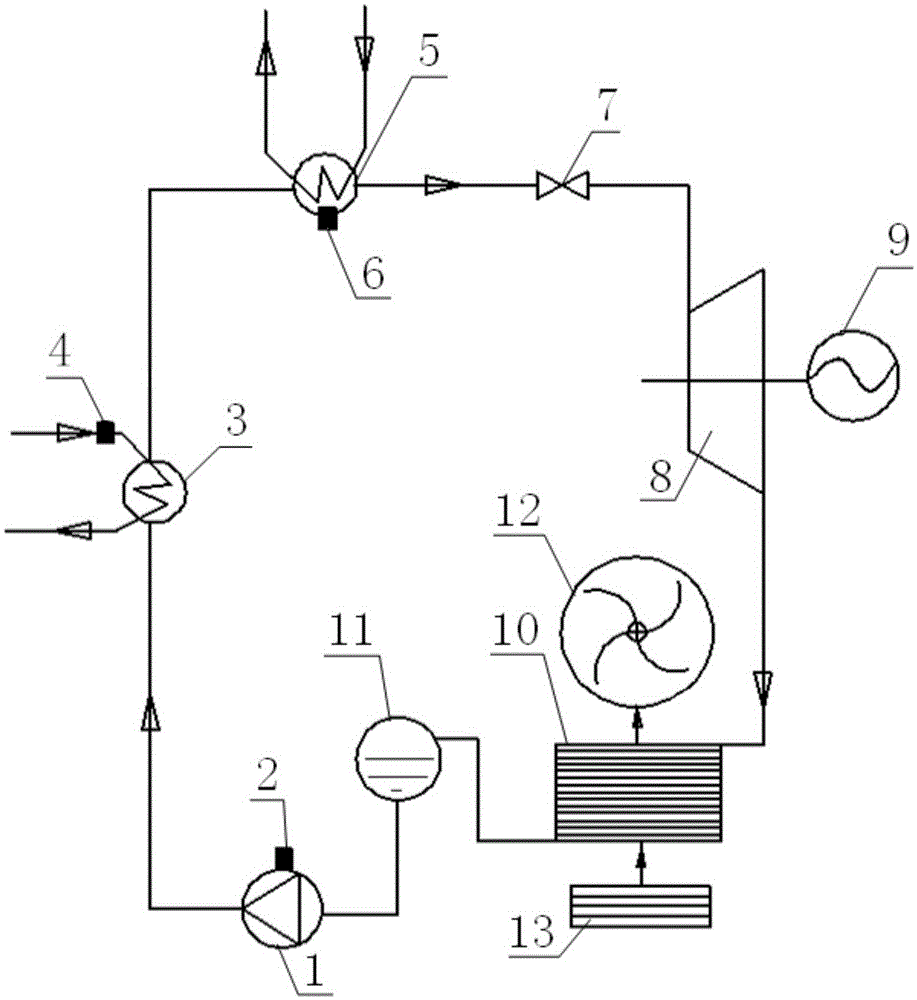
[0020] The present invention will be described in detail below in conjunction with the accompanying drawings.

[0021] Such as figure 1 The automobile engine energy recovery system shown includes an electronically controlled pump 1, a controller 2, a first heat exchanger 3, a coolant temperature sensor 4, a second heat exchanger 5, a working medium temperature sensor 6, a pressure limiting valve 7, A steam turbine 8, an energy recovery mechanism 9, a condenser 10 and a liquid storage tank 11, the controller 2 is integrated and installed on the electronically controlled pump 1, and the first heat exchanger 3 is installed in the cooling system to absorb heat in the cooling system. The heat is used to heat the working medium (such as liquid ammonia). The coolant temperature sensor 4 is installed in the cooling system to detect the temperature of the coolant in the cooling system. The second heat exchanger 5 is installed in the exhaust system for Absorb the exhaust heat in the ex...


PUM


Abstract

The invention discloses an energy recovery system and method for an automobile engine. The energy recovery system for the automobile engine comprises an electric-control pump, a steam turbine, a condenser, a liquid storage tank, a controller, a pressure-limiting valve, an energy recovery mechanism, a first heat exchanger, a coolant temperature sensor, a second heat exchanger and a working medium temperature sensor. The coolant temperature sensor, the working medium temperature sensor and the electric-control pump are electrically connected with the controller. The energy recovery mechanism is installed on an output shaft of the steam turbine. The liquid storage tank, the electric-control pump, the first heat exchanger, the second heat exchanger, the pressure-limiting valve, the steam turbine and the condenser form a circuiting flow channel for working media. In the flowing process of the working media, heat of the engine is absorbed through the first heat exchanger and the second heat exchanger, and the energy recovery mechanism is driven by the steam turbine to recover energy. According to the energy recovery system and method, redundant heat of a cooling system and an exhausting system can be fully recovered, the energy utilization rate of fuel oil is increased, and meanwhile normal cod starting of the engine is prevented from being affected.

Description

technical field [0001] The invention belongs to the technical field of automobile engines, and in particular relates to an energy recovery system and a recovery method of an automobile engine. Background technique [0002] In the process of burning fuel in a car engine, usually 20% to 30% of the energy is taken away by the cooling system, and about 30% of the energy is taken away by the exhaust, and finally only 40% to 50% of the energy is used to drive Automobiles; therefore, recovering engine waste heat (ie energy) is of great significance to improve the fuel energy utilization rate of automobile engines. [0003] When the car is first started, the cooling system is cooler and the catalytic converter needs to be lighted up faster to reduce emissions, so there is less waste heat available. When the engine system reaches the working temperature, the cooling system needs to take away the excess heat of the cylinder block and cylinder head, and the exhaust system takes away t...

Claims


Application Information

Patent Timeline
IPC IPC(8): F02G5/00F02G5/04F01K11/02
CPCY02T10/12
Inventor 杨勇卿辉斌詹樟松
Owner CHONGQING CHANGAN AUTOMOBILE CO LTD
Why Eureka
Try Eureka