A sand blasting machine used in glass production and processing
What is Al technical title?
Al technical title is built by PatSnap Al team. It summarizes the technical point description of the patent document.
A sandblasting machine and sandblasting technology are applied in the direction of metal processing equipment, abrasive jetting machine tools, and used abrasive processing devices, etc., which can solve the problems of low automation, low work efficiency, and bulky volume, and achieve high automation , improve work efficiency, the effect of simple machine structure
Active Publication Date: 2020-07-03
SHENGZHOU HUANDING GLASS TECH CO LTD
View PDF6 Cites 0 Cited by
Summary
Abstract
Description
Claims
Application Information
AI Technical Summary
This helps you quickly interpret patents by identifying the three key elements:
Problems solved by technology
Method used
Benefits of technology
Problems solved by technology
However, there are many deficiencies and shortcomings in the glass sandblasting technology of the prior art: one is bulky and extremely inconvenient for installation and maintenance; , the dust recovery rate is low; fifth, the work efficiency is low, which seriously restricts the development of the glass industry
Method used
Image
Click on the blue label to locate the original text in one second.
Reading with bidirectional positioning of images and text.
Examples
Embodiment Construction
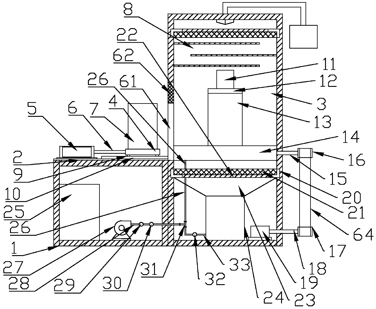
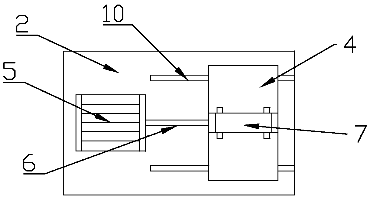
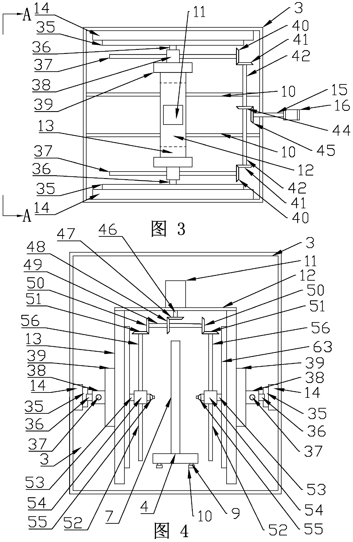
[0029] Such as Figure 1 to Figure 6 As shown, a sandblasting machine used in glass production and processing includes a machine base 1, a conveying workbench 2 and a sandblasting box 3, the conveying workbench 2 is located on the left side of the machine base 1, and the sandblasting box 3 is located on the left side of the machine base 1. Right side of seat 1. The conveying workbench 2 is provided with a conveying device, the conveying device comprises a conveying cylinder 5 and a conveying piston rod 6, the conveying cylinder 5 is connected with the conveying piston rod 6, the other end of the conveying piston rod 6 is connected with a conveying frame 4, and the conveying frame 4 is provided with a Spray glass7. Conveying workbench 2 is provided with conveying track 10, and conveying track 10 is provided with conveying slide block 9, and conveying track 10 matches with conveying slide block 9, and the upper end of conveying slide block 9 connects conveying frame 4. The con...
PUM
Abstract
The invention discloses a sand blasting machine applied to glass production and machining. The sand blasting machine comprises a machine base, a conveying workbench and a sand spray box body. The conveying workbench is located at the left side of the machine base. The sand spray box body is located on the right side of the machine base. Sand spray guns are arranged in the sand spray box body. A vertical moving device is connected to the sand spray guns and comprises a vertically-moving transverse frame and a vertically-moving vertical frame. The vertically-moving transverse frame is connected with the vertically-moving vertical frame. A horizontally-moving device is connected to the outer side of the vertically-moving vertical frame and comprises a horizontally-moving support and a horizontal connection seat. The horizontally-moving support is arranged on the inner wall of the sand spray box body. The vertically-moving vertical frame is fixedly connected to the horizontal connection seat. Through the vertically-moving device and the horizontally-moving device, the sand spray guns can move in the vertical direction and in the horizontal direction at the same time to conduct spray work on glass to be sprayed, so that the sand spray guns can spray sand to the front face and the back face of the glass to be sprayed at the same time, and working efficiency is improved greatly.
Description
technical field [0001] The invention relates to the technical field of glass production and processing, and specifically refers to a sandblasting machine applied to glass production and processing. Background technique [0002] Sand blasting is a conventional, abrasive jet technology, which has been continuously developed, improved and perfected. With its unique processing mechanism and wide range of applications, it has become more and more popular in today's surface treatment industry and is widely used. It is widely used in machinery manufacturing, instrumentation, medical equipment, electronic appliances, textile machinery, printing and dyeing machinery, chemical machinery, food machinery, tools, blades, measuring tools, molds, glass, ceramics, handicrafts, mechanical repairs and many other fields. [0003] In modern architecture and decoration, glass is widely used in people's production and life because of its gorgeousness, beauty, and various forms. Specifically, ther...
Claims
Application Information
Patent Timeline
Application Date:The date an application was filed.
Publication Date:The date a patent or application was officially published.
First Publication Date:The earliest publication date of a patent with the same application number.
Issue Date:Publication date of the patent grant document.
PCT Entry Date:The Entry date of PCT National Phase.
Estimated Expiry Date:The statutory expiry date of a patent right according to the Patent Law, and it is the longest term of protection that the patent right can achieve without the termination of the patent right due to other reasons(Term extension factor has been taken into account ).
Invalid Date:Actual expiry date is based on effective date or publication date of legal transaction data of invalid patent.