
Gas distributor applied to film deposition technique

A gas distributor and gas distribution technology, applied in the direction of gaseous chemical plating, metal material coating process, coating, etc., can solve the problems such as difficult to clean, uneven gas at the end of the pipeline, etc., to save the consumption of reaction gas , reduce the purge time, avoid the effect of reaction

Active Publication Date: 2016-02-24
BEIJING NAURA MICROELECTRONICS EQUIP CO LTD
View PDF5 Cites 7 Cited by
  • Summary
  • Abstract
  • Description
  • Claims
  • Application Information

AI Technical Summary

Problems solved by technology

Although the double-layer network structure of the gas distributor disclosed in this invention patent application can realize the independent access of the two reaction sources, since the gas distributor pipelines of each layer are all equal diameters (or equal cross-sectional areas), it is easy to cause the end of the pipeline to be damaged. The gas pressure gradually decreases and the phenomenon of gas inhomogeneity occurs; at the same time, due to the influence of the pressure reduction and flow reduction in the pipeline, the purge gas is not easy to clean the previous gas remaining in the pipeline here, so that CVD reactions are easily mistaken

Method used


Image

  • Gas distributor applied to film deposition technique
  • Gas distributor applied to film deposition technique
  • Gas distributor applied to film deposition technique

Examples


Embodiment Construction

[0024] The specific embodiment of the present invention will be further described in detail below in conjunction with the accompanying drawings.

[0025] It should be noted that, in the following specific embodiments, when describing the embodiments of the present invention in detail, in order to clearly show the structure of the present invention for the convenience of description, the structures in the drawings are not drawn according to the general scale, and are drawn Partial magnification, deformation and simplification are included, therefore, it should be avoided to be interpreted as a limitation of the present invention.

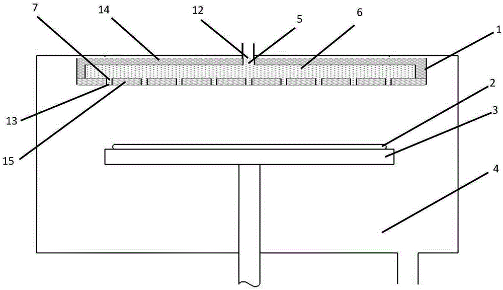
[0026] In the following specific embodiments of the present invention, please refer to figure 1 , figure 1 It is a schematic diagram of the installation structure of a gas distributor applied to thin film deposition technology located in the reaction chamber of atomic layer deposition equipment according to a preferred embodiment of the present inve...


PUM


Abstract

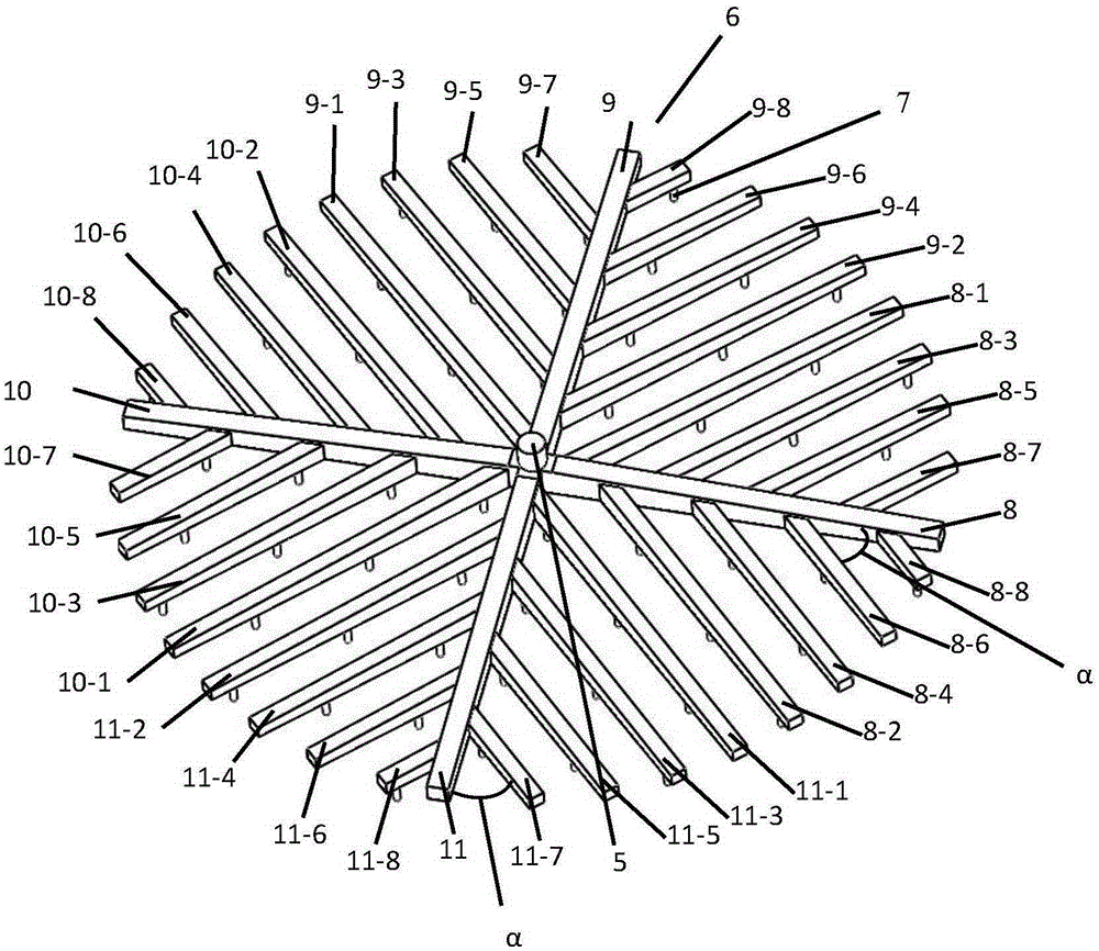
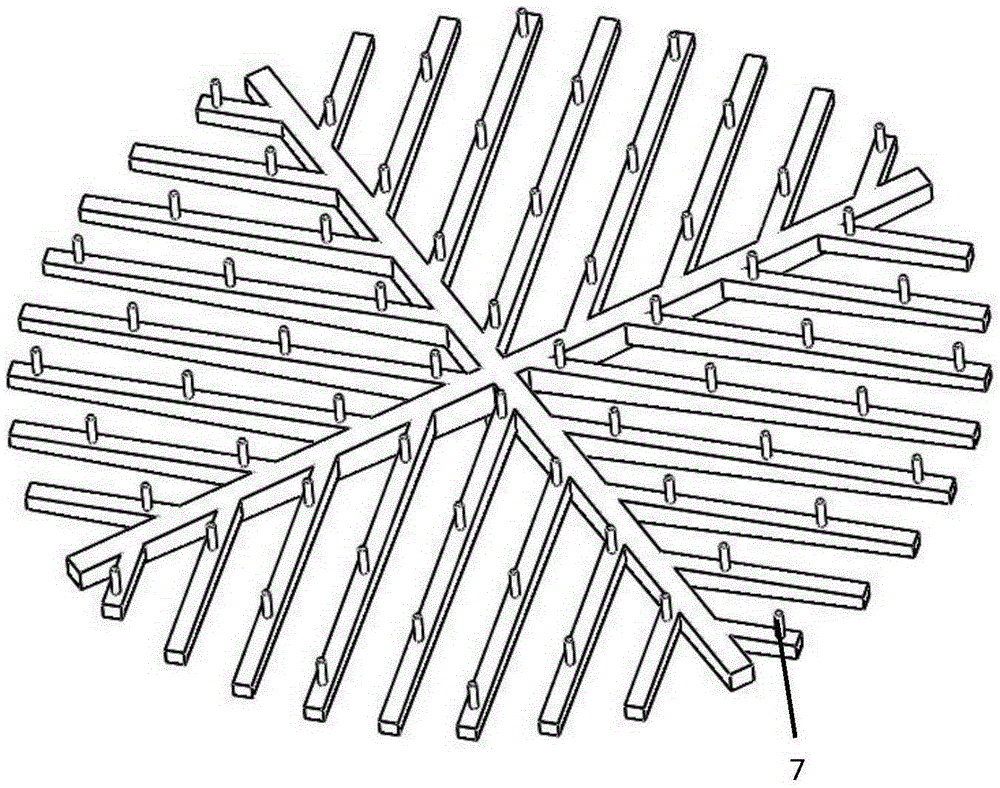
The invention discloses a gas distributor applied to a film deposition technique. Radial gas distribution main pipes are arranged in a body, gas distribution branch pipes are arranged on both sides of the gas distribution main pipes in a staggered mode, the cross sectional areas of pipelines are gradually reduced from the gas distribution main pipes to the gas distribution branch pipes, so that a tree-shaped gas distribution network is formed, reactant gas or vapor from a gas inlet pipe of a gas distribution network center can be vertically and uniformly blown to the surface of a covered silicon wafer through a plurality of gas outlet pipes which are regularly distributed, the homogeneous reaction on the covered silicon can be realized, the reaction efficiency can be improved, the consumption of the reactant gas and the size of equipment can be reduced, residual gas at the edge of the gas distribution network can be easily blown out by blowing gas, and the CVD (Chemical Vapor Deposition) reaction in the ALD (Atomic Layer Deposition) reaction is effectively prevented. The gas distributor has the obvious characteristics that the yield and qualified rate of the ALD reaction are increased, and the cost is reduced.

Description

technical field [0001] The invention relates to the technical field of semiconductor atomic layer deposition, and more specifically relates to a gas distributor applied to semiconductor atomic layer deposition technology that can evenly distribute reaction gas and prevent chemical vapor deposition reactions from erroneously occurring during atomic layer deposition. Background technique [0002] At present, thin film deposition reaction systems and methods are widely used in devices in various fields, such as: semiconductors, integrated circuits, solar panels, flat-panel displays, microelectronics, light-emitting diodes, and the like. Forming a thin film of 10 μm or less on the surface of a substrate by chemical vapor deposition (Chemical Vapour Deposition, CVD) technology is a common method for thin film deposition. Most CVD technologies generally need to provide a variety of gases or vapors to deposit and form films in order to obtain the desired performance and chemical co...

Claims


Application Information

Patent Timeline
Patent Type & Authority Applications(China)
IPC IPC(8): C23C16/455
CPCC23C16/455
Inventor 苏艳波赵星梅克雷格·伯考兰云峰
Owner BEIJING NAURA MICROELECTRONICS EQUIP CO LTD
Learn More