Color wheel and laser light source

A color wheel and laser technology, used in optics, instruments, projection devices, etc., can solve the problems of complex control of dual-wavelength conversion devices, high processing and assembly requirements, and increased software complexity. The effect of miniaturization and improved color filter purity

Inactive Publication Date: 2016-02-24
HISENSE
View PDF3 Cites 18 Cited by
  • Summary
  • Abstract
  • Description
  • Claims
  • Application Information

AI Technical Summary

Problems solved by technology

[0007] Therefore, in order to maintain synchronization, one method is to set the two devices coaxially and share a set of drive motors, but the processing and assembly requirements are high, and the production yield is low. The other method is non-coaxial, and two sets of drive motors are used for distributed drive. However, it is necessary

Method used


Image

  • Color wheel and laser light source
  • Color wheel and laser light source
  • Color wheel and laser light source

Examples


Embodiment 1

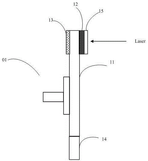
[0036] Embodiment 1 of the present invention provides a color wheel that receives laser irradiation and rotates under control, generally using a blue laser as the laser excitation light. Such as image 3 As shown, the color wheel 01 includes a substrate 11 on which a fluorescent area 12 and a transmissive area 14 are arranged. The fluorescent area 12 includes phosphor powder for generating fluorescence when irradiated by blue laser light, and the transmissive area 14 is used for transmitting blue laser light.

[0037] In one implementation, the color wheel is a transmissive fluorescent wheel, see image 3 , the substrate 11 is a transparent substrate, such as made of glass material, and has light transmission performance. The phosphor area 12 may be a phosphor layer on the transparent substrate, and the phosphor layer 12 and the transparent substrate are bonded by silica gel, which has high temperature resistance. Specifically, the phosphor layer 12 may be a fan-shaped area ...

Embodiment 2

[0048] Embodiment 2 of the present invention provides a color wheel. The difference from Embodiment 1 is that the color wheel in this embodiment is a reflective fluorescent wheel, that is, the excited fluorescence is along the direction opposite to the incident direction of the laser light. Shooting from the front of the color wheel.

[0049] Specifically, see Figure 7 , the color wheel 01 includes a substrate 11, wherein the substrate 11 is a mirror aluminum substrate, the surface of which can reflect light. The substrate 11 includes a fluorescent area 12 and a transmissive area 14. The fluorescent area 12 includes a phosphor, usually a phosphor layer, which is glued to the laser light-incident side surface of the aluminum substrate to generate fluorescence when irradiated by blue laser light. Fluorescent light can be reflected by at least part of the above-mentioned mirror aluminum substrate, so as to emerge along the front of the color wheel. It should be noted that the m...

Embodiment 3

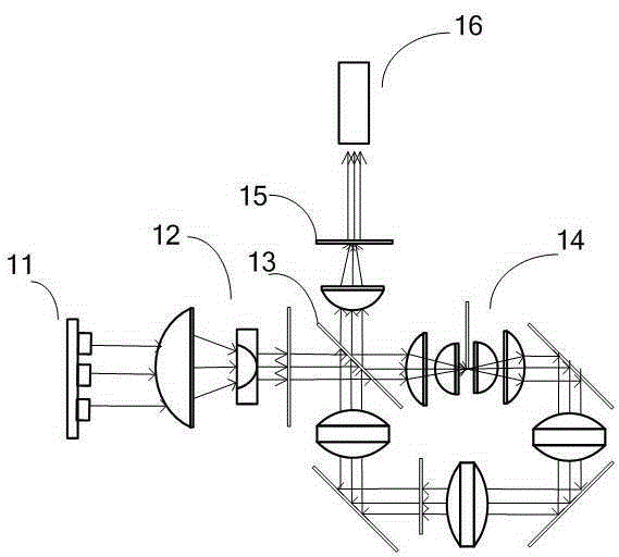
[0057] Embodiment 3 of the present invention provides a laser light source, such as Figure 8 As shown, it includes a laser group 01, specifically including a blue laser 11 and a red laser 12, which respectively emit blue laser and red laser; and a color wheel 20, wherein the color wheel 20 can be the color wheel exemplified in the above-mentioned embodiment 1 , the color wheel 20 is a transmissive phosphor wheel. Specifically, the color wheel 20 is provided with a green fluorescent powder, which can receive blue laser light and be excited to produce green fluorescence.

[0058] The blue laser needs to undergo beam shaping, such as beam reduction and homogenization, to form a smaller spot that meets the fluorescence excitation requirements, and then incident on the surface of the color wheel 20, the color wheel 20 rotates periodically, and the blue laser is incident on the color wheel in turn 20 green phosphor area and transmission area (not shown in the figure, can refer to ...


PUM


Abstract

The invention discloses a color wheel which receives laser radiation and is controlled to rotate. The color wheel comprises a base plate, wherein a fluorescence area and a transmission area are formed in the base plate; the fluorescence area comprises fluorescent powder and is used for being excited to generate fluorescence; the transmission area is used for transmitting laser; a color filter is arranged in the partial base plate surface area which corresponds to the fluorescence outlet side and is used for filtering the transmitted fluorescence, so that the color filtering effect is guaranteed, use of a filtering device is saved, the technical problem that an optical system, particularly a light source, is large in size is solved, and the color wheel is multifunctional. The invention also provides a laser light source structure applying the color wheel. The light source size and system control complexity can be reduced, and the product competitiveness is improved.

Description

technical field [0001] The invention relates to the field of light source lighting, in particular to a color wheel and a laser light source. Background technique [0002] Laser is a light source with high brightness, strong directionality, and monochromatic coherent light beam. Due to its many advantages, it has been gradually used as a light source in the field of projection display technology in recent years. [0003] Such as figure 1 , which shows a schematic structural diagram of a laser light source composed of laser light and fluorescence generated by laser-excited phosphors, including a laser array 11 that emits laser light, and the laser beam is shrunk and homogenized by a beam shaping system 12. The transmission of the dichroic sheet 13 reaches the wavelength conversion device 14, wherein the wavelength conversion device 14 is coated with phosphor powder, and the laser beam irradiates and excites the phosphor powder to generate fluorescence of a corresponding color...

Claims


Application Information

Patent Timeline
IPC IPC(8): G03B21/20
CPCG03B21/204
Inventor 赵飞
Owner HISENSE
Why Eureka
Try Eureka