Surface mounting inductor manufacture method

A technology of surface mounting and manufacturing methods, applied in the direction of inductor/transformer/magnet manufacturing, coil manufacturing, transformer/inductor coil/winding/connection, etc., can solve the problem of large DC resistance, increased resistance of surface mounted inductors, and discharge of organic matter Insufficient and other problems, to achieve the effect of reducing DC resistance, high performance, and small DC resistance

Inactive Publication Date: 2016-02-24
NINGBO YUNSHENG ELECTRONIC COMPONENTS TECHNOLOGY CO LTD +1
View PDF7 Cites 16 Cited by
  • Summary
  • Abstract
  • Description
  • Claims
  • Application Information

AI Technical Summary

Problems solved by technology

The terminal silver process has become the main process used in the current surface mount inductor manufacturing method, but the surface mount inductors prepared by the terminal silver process have the following problems: the silver paste is made of silver powder and organic matter, and it needs to be sintered at high temperature to be sintered. The organic matter is discharged, and the inductance element cannot use the high-temperature sintering process because there is a coil wound with enameled wire inside. Although a silver paste that can be degummed at about 250 ° C has been developed, the organic matter is not discharged sufficiently. Therefore, in the electrode It must contain a small amount of organic matter, and the presence of a small amount of organic matter will cause the DC resistance between the lead wire of the coil and the electrode (R DC ) is relatively large, the resistance of surface mount inductors increases significantly, which affects the performance of surface mount inductors

Method used


Image

  • Surface mounting inductor manufacture method
  • Surface mounting inductor manufacture method
  • Surface mounting inductor manufacture method

Examples


Embodiment 1

[0049] Embodiment 1: As shown in the figure, a method for manufacturing a surface mount inductor includes the following steps:

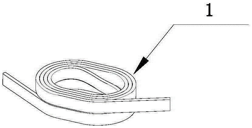
[0050] ① According to the design specifications, the enameled wire with self-adhesive layer is wound into a hollow coil 1 with leads 11 at both ends; the adhesion temperature of the self-adhesive layer of the enameled wire is 80°C to 220°C, and the temperature resistance level of the enameled wire is 155°C to 255°C .

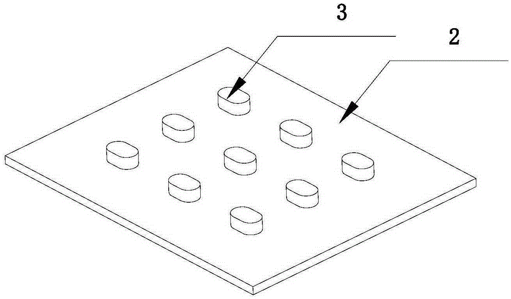
[0051] ② The base is made of magnetic powder, and the base includes a base 2 and N bosses 3 or N grooves arranged on the base 2 and arranged at intervals in an array, where N is an integer greater than or equal to 2;

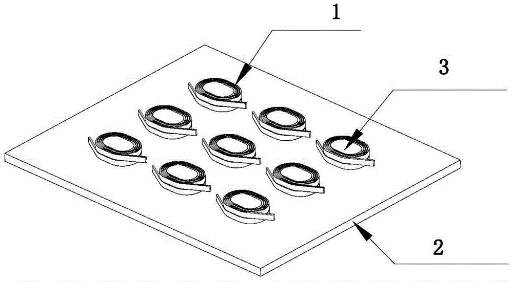
[0052] ③ Assemble the air-core coil 1 and the base: place N air-core coils 1 on the outside of N bosses 3 one by one or place N air-core coils 1 in N grooves one by one to obtain N air-core coils 1 In the assembly with the base, the N air-core coils 1 in the assembly with the base are also arranged in an array, and ther...

Embodiment 2

[0060] Embodiment 2: As shown in the figure, a method for manufacturing a surface mount inductor includes the following steps:

[0061] ① According to the design specifications, the enameled wire with self-adhesive layer is wound into a hollow coil 1 with leads 11 at both ends; the adhesion temperature of the self-adhesive layer of the enameled wire is 80°C to 220°C, and the temperature resistance level of the enameled wire is 155°C to 255°C .

[0062] ② The base is made of magnetic powder, and the base includes a base 2 and N bosses 3 or N grooves arranged on the base 2 and arranged at intervals in an array, where N is an integer greater than or equal to 2;

[0063] ③ Assemble the air-core coil 1 and the base: place N air-core coils 1 on the outside of N bosses 3 one by one or place N air-core coils 1 in N grooves one by one to obtain N air-core coils 1 In the assembly with the base, the N air-core coils 1 in the assembly with the base are also arranged in an array, and ther...

Embodiment 3

[0072] Embodiment 3: As shown in the figure, a method for manufacturing a surface mount inductor includes the following steps:

[0073] ① According to the design specifications, the enameled wire with self-adhesive layer is wound into a hollow coil 1 with leads 11 at both ends; the adhesion temperature of the self-adhesive layer of the enameled wire is 80°C to 220°C, and the temperature resistance level of the enameled wire is 155°C to 255°C .

[0074] ② The base is made of magnetic powder, and the base includes a base 2 and N bosses 3 or N grooves arranged on the base 2 and arranged at intervals in an array, where N is an integer greater than or equal to 2;

[0075] ③ Assemble the air-core coil 1 and the base: place N air-core coils 1 on the outside of N bosses 3 one by one or place N air-core coils 1 in N grooves one by one to obtain N air-core coils 1 In the assembly with the base, the N air-core coils 1 in the assembly with the base are also arranged in an array, and ther...


PUM

PropertyMeasurementUnit
particle diameteraaaaaaaaaa

Abstract

The invention discloses a surface mounting inductor manufacture method comprising the following steps: firstly preparing an inductor body; carrying out insulation treatment for the surface of the inductor body besides an electrode portion; pre-processing the electrode portion of the inductor body; removing an insulation layer on end portions of two lead wires of a coil in the inductor body; depositing one or more layers of metal conductive layers on the surface of the electrode portion of the inductor body through either a physics vapour deposition technology, or chemical vapor deposition or electroplate and chemical plating technology, the metal conductive layers are the electrode, thus obtaining the surface mounting inductor; the advantages are that the electrode position mode is employed to form the electrode, the electrode can directly grow into form on the electrode portion of the inductor body, and the electrode can be directly deposited on the end portion of the lead wires of the coil in a forming process; the electrode and the lead wires are connected through atom combination so as to provide high connecting integration, thus greatly reducing DC resistance between the lead wires of the coil and the electrode; the DC resistance between the lead wires of the coil and the electrode is relatively small, so the performance of the surface mounting inductor is high.

Description

technical field [0001] The invention relates to a preparation technology of surface mount inductors, in particular to a manufacturing method of surface mount inductors. Background technique [0002] Inductor is one of the three major passive components of electronic circuits. In the circuit, it mainly plays the role of filtering, oscillation, delay, notch, filtering signal, filtering noise, stabilizing current and suppressing electromagnetic wave interference. With the rapid development of electronic technology, especially the rapid popularization of mobile consumer electronics terminals, inductance devices are developing in the direction of miniaturization, lightness, high frequency, high current, high efficiency, and low EMI. Surface mount inductors have achieved Wide range of applications. [0003] Existing surface mount inductors mainly include an inductance body and two electrodes covering both ends of the inductance body. We call the part where the two ends of the ind...

Claims


Application Information

Patent Timeline
Patent Type & Authority Applications(China)
IPC IPC(8): H01F41/00H01F41/04H01F1/147H01F1/20H01F27/30
Inventor 徐文正蔡平平向明亮陈宏杰钱征宇
Owner NINGBO YUNSHENG ELECTRONIC COMPONENTS TECHNOLOGY CO LTD
Why Eureka
Try Eureka