
Double-face double-magnetic-circuit transverse flux linear permanent magnet motor

A technology of transverse flux and permanent magnet motors, applied in the direction of magnetic circuits, electromechanical devices, electrical components, etc., can solve the problems of complex structure of transverse flux linear permanent magnet motors, difficult processing and assembly, and increased output force pulsation. Achieve the effect of small positioning force, high motor reliability and small fluctuation of motor output force

Inactive Publication Date: 2016-02-24
SHANDONG UNIV
View PDF3 Cites 5 Cited by
  • Summary
  • Abstract
  • Description
  • Claims
  • Application Information

AI Technical Summary

Problems solved by technology

[0003] The thrust of conventional transverse flux linear permanent magnet motors can be greater than that of ordinary linear motors. However, as the thrust of the motor increases, the output force pulsation also increases. In addition, the general transverse flux linear permanent magnet motor has a complex structure and is difficult to process and assemble.
Generally, flat-plate transverse flux linear permanent magnet motors still have the problem of unilateral magnetic pull.

Method used


Image

  • Double-face double-magnetic-circuit transverse flux linear permanent magnet motor
  • Double-face double-magnetic-circuit transverse flux linear permanent magnet motor
  • Double-face double-magnetic-circuit transverse flux linear permanent magnet motor

Examples


Embodiment Construction

[0037] The present invention will be further described below in conjunction with the accompanying drawings and embodiments.

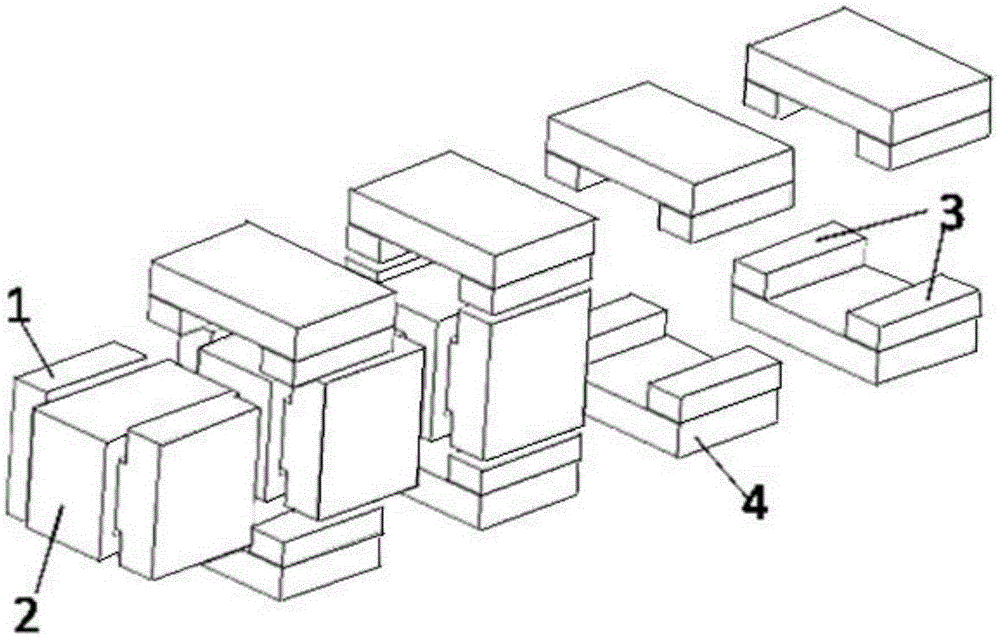
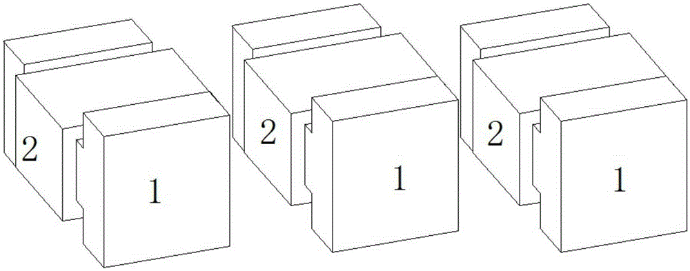
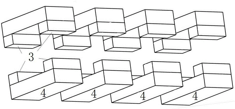
[0038] The double-sided transverse flux linear permanent magnet motor is a multi-phase linear motor with M phases, and the primary unit windings of the same phase can be connected in parallel or in series. figure 1 Shown is a three-dimensional schematic diagram of a double-sided transverse flux linear permanent magnet motor. As shown in the figure, the primary unit of the motor includes an "I"-shaped magnetic material 1 and a coil wound on the "I"-shaped magnetic material. The winding 3 and the secondary part of the motor are composed of secondary units, each of which includes a magnetically conductive plate 4 and two permanent magnets 3 . The secondary is arranged on both sides of the primary of the motor. figure 2 The three-dimensional view of the primary part of the motor is shown, and the primary units are arranged in sequence along the direction ...


PUM


Abstract

The invention discloses a double-face double-magnetic-circuit transverse flux linear permanent magnet motor. The motor comprises a primary part, a second part and air gaps; and the primary part is composed of a plurality of primary units having the same structure, each primary unit is composed of a magnetic conducting material and a coil winding, and the magnetic conducting material can be formed through lamination of silicon steel sheets or be composed of a composite magnetic conducting material in a forging and stamping manner. The primary units are successively arranged on an operation direction, the number of the primary units is an integer times of the motor phase number, and windings in the same-phase primary units are mutually connected in parallel or in series. The secondary part is composed of a plurality of secondary units having the same structure, each secondary unit comprises a magnetic conducting plate and two permanent magnets, the secondary units are arranged on the two sides of the primary units in a paired symmetrical manner to form a double-face structure, and two parallel magnetic circuits are formed between the primary units and the secondary units on the two sides of the primary units. The double-face double-magnetic-circuit transverse flux linear permanent magnet motor has the advantages of the short magnetic circuits, less loss and large force density, the double-face double-magnetic-circuit transverse flux linear permanent magnet motor can be taken as a motor and also can be taken as a generator, and the double-face double-magnetic-circuit transverse flux linear permanent magnet motor has a wide application prospect.

Description

technical field [0001] The invention relates to a double-sided double magnetic circuit transverse magnetic flux linear permanent magnet motor. Background technique [0002] The motion direction of the transverse flux linear permanent magnet motor is perpendicular to the plane where the motor magnetic field path is located. The motor circuit and the motor magnetic circuit are relatively independent. Compared with the traditional motor, the transverse flux motor has high torque density, flexible design, and low electromagnetic load. With the characteristics of decoupling, convenient control, and excellent low-speed characteristics, its application fields are also expanding, especially suitable for low-speed and high-power drive occasions. The transverse flux motor greatly shortens the length of the magnetic circuit, reduces the amount of ferromagnetic materials and iron loss. , within a certain range, the rate of change of magnetic energy is increased, thereby increasing the o...

Claims


Application Information

Patent Timeline
IPC IPC(8): H02K41/03
CPCH02K41/031H02K2201/12
Inventor 徐衍亮付东山
Owner SHANDONG UNIV
Learn More