High-speed atomizer based on magnetic suspension bearing permanent magnet synchronous motor

A permanent magnet synchronous motor and magnetic suspension bearing technology, applied in the field of atomizers, can solve the problems of large rotor speed regulation range, easy wear and tear of the atomizer, and high operating costs, and achieves high operation reliability, suppression of external interference and system. Vibration, low running cost effect

Inactive Publication Date: 2016-03-02
ACRE COKING & REFRACTORY ENG CONSULTING CORP +1
View PDF9 Cites 8 Cited by
  • Summary
  • Abstract
  • Description
  • Claims
  • Application Information

AI Technical Summary

Problems solved by technology

[0008] The invention provides a high-speed atomizer based on a permanent magnet synchronous motor with a magnetic suspension bearing. The permanent magnet synchronous high-speed motor integrating a high-power high-frequency power supply and a magnetic suspension bearing is used to directly drive the atomization wheel. The rotor speed adjustment range is large. Moreover, the rotor shaft is completely supported by the magnetic suspension bearing when it rotates at high speed, and does not directly contact with other parts, so no lubrication is required; it completely solves the problems of easy wear, short life and high operating cost of the existing atomizer

Method used


Image

  • High-speed atomizer based on magnetic suspension bearing permanent magnet synchronous motor
  • High-speed atomizer based on magnetic suspension bearing permanent magnet synchronous motor
  • High-speed atomizer based on magnetic suspension bearing permanent magnet synchronous motor

Examples


Embodiment Construction

[0027] The specific embodiment of the present invention will be further described below in conjunction with accompanying drawing:

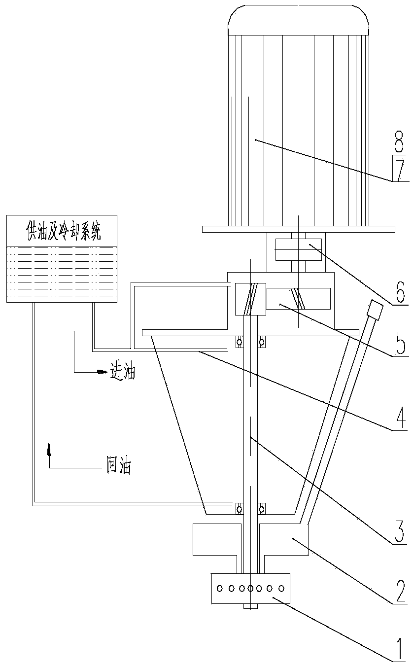
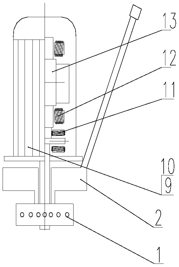
[0028] See figure 2 , is a structural schematic diagram of the present invention, a high-speed atomizer based on a magnetic suspension bearing permanent magnet synchronous motor of the present invention, including a permanent magnet synchronous motor 9, an atomizer feeding and distributing mechanism 2 and an atomizing wheel 1; the permanent magnet The synchronous motor 9 is integrated with a high-frequency power supply 10, and the permanent magnet synchronous motor 9 is provided with a magnetic levitation radial bearing 11 and a magnetic levitation axial bearing 12 to provide radial and axial support for the motor shaft 13; The atomizer feeding and distributing mechanism 2 and the atomizing wheel 1, the atomizer feeding and distributing mechanism 2 are composed of a distributor and a feeding pipe.

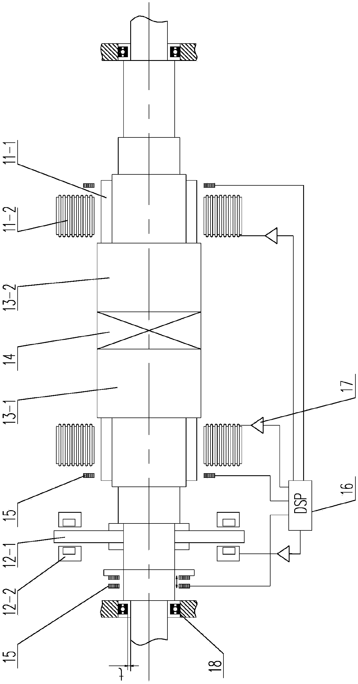
[0029] Such as image 3 As shown, the motor s...


PUM


Abstract

The invention relates to a high-speed atomizer based on a magnetic suspension bearing permanent magnet synchronous motor. The high-speed atomizer comprises a permanent magnet synchronous motor, a loading and distributing mechanism of the atomizer and an atomizing wheel, wherein the permanent magnet synchronous motor is integrated with a high-frequency power supply; a magnetic suspension radial bearing and a magnetic suspension axial bearing are arranged in the permanent magnet synchronous motor to provide radial and axial support for a motor shaft; the extending-out end of the motor shaft is sequentially provided with the loading and distributing mechanism of the atomizer and the atomizing wheel in a sleeving mode; and the loading and distributing mechanism of the atomizer is composed of a distributor and a feeding tube. The high-speed atomizer adopts the permanent magnet synchronous high-speed motor which is integrated with a large-power high-frequency power supply and magnetic suspension bearings to directly drive the atomizing wheel, so that speed regulation range for the rotation speed of a rotor is large; when rotating at a high speed, a rotor shaft is completely supported by the magnetic suspension bearings, and is not in direct contact with other parts, so that lubricating is not required, and therefore, the problems of easy abrasion, a short service life, high operation cost and the like of a current atomizer are completely solved.

Description

technical field [0001] The invention relates to an atomizer, in particular to a high-speed atomizer based on a magnetic suspension bearing permanent magnet synchronous motor. Background technique [0002] Such as figure 1 As shown, the currently commonly used rotary atomizer is generally composed of an atomizing wheel 1, a feeding and distributing mechanism 2, a transmission shaft 3, a machine base 4, a speed-up gearbox 5, a coupling 6, a motor 7 and a frequency converter 8 In addition, oil supply and cooling systems need to be configured, which have the following problems in use: [0003] 1) The structure of the equipment is complex and there are many failure points. Due to the high-speed rotation, the core mechanical parts such as transmission and speed increase are very easy to wear, resulting in short life and high maintenance costs; [0004] 2) Lubricating oil is required for both the gearbox and the main shaft components, and it rotates at a high speed (more than 10,...

Claims


Application Information

Patent Timeline
Patent Type & Authority Applications(China)
IPC IPC(8): B05B3/10H02K21/02
CPCB05B3/1035H02K7/003H02K21/02
Inventor 王充尹华吕文彬安振刚张永学
Owner ACRE COKING & REFRACTORY ENG CONSULTING CORP
Why Eureka
Try Eureka